12
Base Stand and Wheel Set Installation
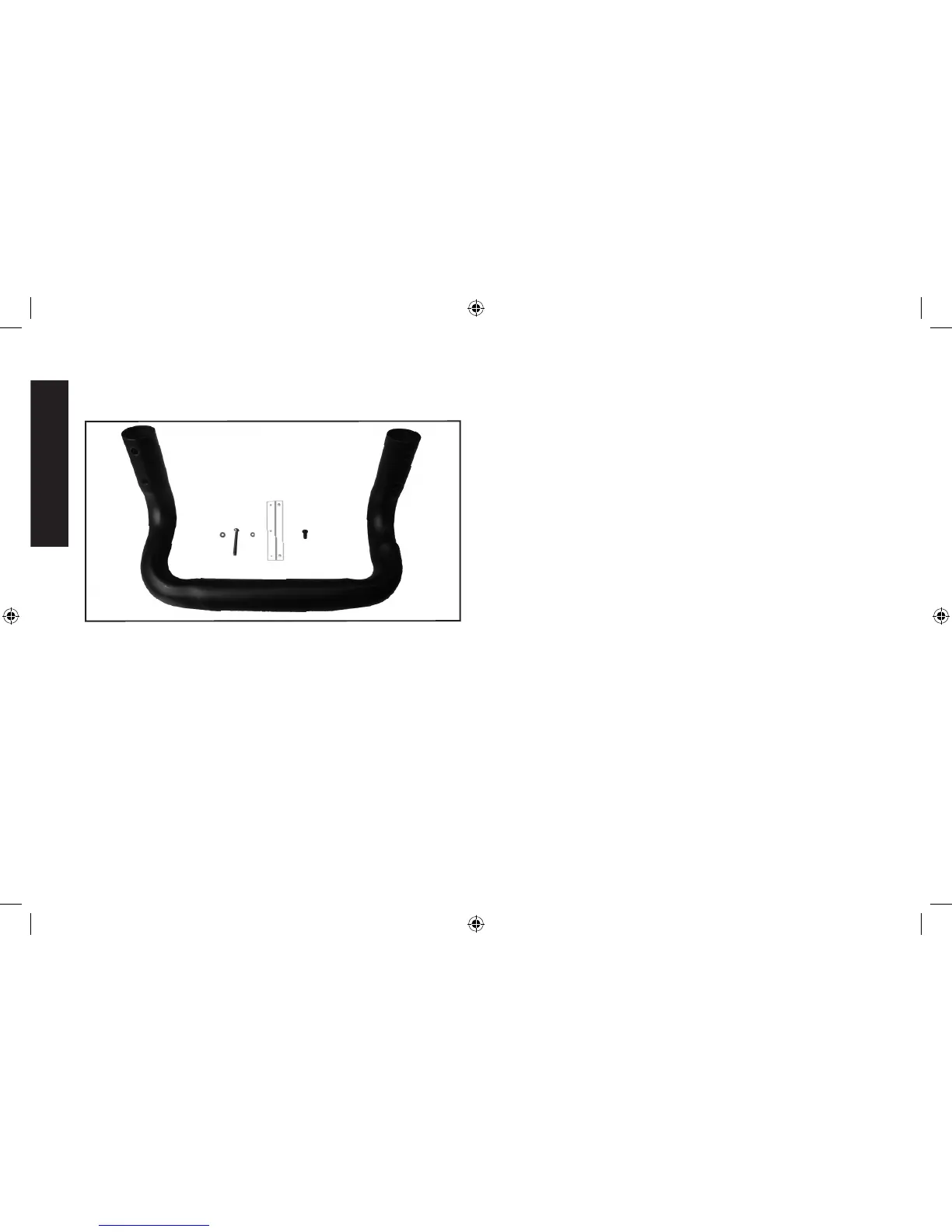
PARTS:
A
B
C
D F
E
A. Base Stand
B. Ø4mm Plain Washer
(4 in total)
C. Base Stand Screw
(4x22mm) (4 in total)
D. Ø4mm Spring Washer
(7 in total: 4 for Base Stand,
3 for Wheel Set Lock)
E. Wheel Set Lock
F. Wheel Set Lock Screw
(4x8mm) (3 in total)
ASSEMBLY:
1. Turn the unit upside down with the unit base at top as shown.
2. Position the Base Stand as shown in the illustration on the following
page, aligning the four Base Stand Screws, Ø4mm Spring Washers
and Ø4mm Plain Washers with the Base Stand Screw Holes
through the apertures on the Base Stand in the sequence shown
in the illustration.
3. Screw the four Base Stand Screws into the Base Stand Screw
Holes. Do not over-tighten.
4. Position the Wheel Set Assembly as shown in the illustration.
5. Align the Wheel Set Lock with the three Wheel Set Screw Holes. It
should be centered over the Wheel Shaft Slots.
6. Screw the three Wheel Set Lock Screws with the three Ø4mm
Spring Washers in the sequence shown in the illustration into the
Wheel Lock Screw Holes through the Wheel Set Lock. Do not
over-tighten.
DXAEC210_ManualENFRSP_092116.indd 12 10/19/2016 3:58:54 PM