EasyManua.ls Logo

Dexter Laundry Wn0600xa-12en2x-sskcs-usx User Manual

Dexter Laundry Wn0600xa-12en2x-sskcs-usx
159 pages
To Next Page IconTo Next Page
Page #1 background imageLoading...
Page #1 background image
8533-097-001 (11/16)
OPL 30 Cycle 100G
PARTS & SERVICE MANUAL
Including Electric & Steam Heated Models 50Hz. & 60Hz.

Table of Contents

Question and Answer IconNeed help?

Do you have a question about the Dexter Laundry Wn0600xa-12en2x-sskcs-usx and is the answer not in the manual?

Dexter Laundry Wn0600xa-12en2x-sskcs-usx Specifications

General IconGeneral
BrandDexter Laundry
ModelWn0600xa-12en2x-sskcs-usx
CategoryWasher
LanguageEnglish

Summary

Equipment Safety Warnings Symbols and Terminology

Safety Symbol Definitions

Definitions for DANGER, WARNING, CAUTION, and NOTICE safety symbols.

Specific Hazard Symbols and Cautions

Descriptions of user caution, electrical hazard, sharp edges, and ATEX environment symbols.

Dexter Safety Guidelines and General Warnings

Essential Safety Precautions

Key safety guidelines for operating the equipment.

Operational Warning

A critical warning regarding safe operation.

Section 1: Machine Dimensions

Mounting Dimensions for T-600, T-900, and T-1200 Models

T-600 Mounting Dimensions

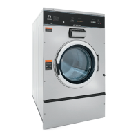
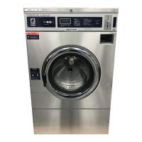
Detailed mounting dimensions for the T-600 model.

T-900 Mounting Dimensions

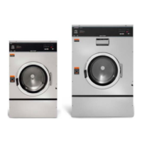
Detailed mounting dimensions for the T-900 model.

T-1200 Mounting Dimensions

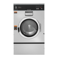
Detailed mounting dimensions for the T-1200 model.

Mounting Pad Dimensions

T-600 Mounting Pad Dimensions

Specifications for the T-600 mounting pad.

T-900 Mounting Pad Dimensions

Specifications for the T-900 mounting pad.

T-1200 Mounting Pad Dimensions

Specifications for the T-1200 mounting pad.

Section 2: Machine Installation & Operating Instructions

Installation and Operation Guidelines

Foundation and Mounting Requirements

Guidelines for proper foundation and mounting procedures.

Plumbing, Drain, and Electrical Setup

Requirements for water supply, drainage, and electrical connections.

Fusing Requirements and Controls Transformer

Fusing Requirements

Specifications for fuses or breakers.

Controls Transformer Details

Information on the controls transformer.

Liquid Chemical Connection and Injection

Liquid Chemical Connection Points

Details on connecting chemical hoses and signals.

Injection Source Programming

How to program chemical injection sources.

Washer Operating Instructions

Push-button Control Switch Functions

Explanation of the STOP, START, SCROLL UP, and SCROLL DOWN buttons.

Operating Instructions Details and Safety Features

Step-by-Step Operation and Soak Feature

Detailed operation steps and the soak function.

End of Cycle Indicators and Safety Door Lock

Information on end-of-cycle signals and the door lock mechanism.

Computer Control Indicators and Bath Setting Limits

Computer Control Indicators Overview

Explanation of computer control indicators.

Programmable Bath Setting Limits

Limits for cycle time, water temperature, level, injection, and spin.

Section 3: Machine Programming Instructions

Programming Instructions: Editing Existing Cycles

Cycle Selection and Segment Editing

Steps to select and edit cycle segments.

Editing Cycle Time and Water Temperature

Adjusting cycle time and water temperature parameters.

Editing Water Level and Injection Source

Adjusting water level and injection source settings.

Spin Time Editing and Cycle Times Summary

Editing Spin Time Settings

Procedure for adjusting spin time.

Cycle Times Overview

Summary table of cycle segment timings.

30 Preset Wash Cycles Overview

Shirt/Laundry, Hotel/Motel, and Health Care Cycles

Descriptions of cycles for specific applications.

Food & Beverage, Other, and Test Cycles

Descriptions of cycles for specific applications.

Section 4: Trouble Shooting Guide

Rapid Advance Mode Procedures

Entering and Exiting Rapid Advance Mode

Steps to enter, use, and exit the rapid advance mode.

Notes on Rapid Advance Mode Operation

Important operational notes and limitations for rapid advance.

Diagnostic Test Cycle (#31) Operation

Operating the Diagnostic Test Cycle

Step-by-step instructions for running the diagnostic cycle.

Component Testing and Cycle Reset

Procedures for testing components and resetting cycles.

Input/Output PCB Board Schematic

Microprocessor PCB Board Schematic

Common Troubleshooting Solutions

Machine Start, Stop, and Door Lock Issues

Troubleshooting for start, stop, and door lock problems.

Machine Start/Stop and Door Lock Issues

Troubleshooting for start/stop and door lock failures.

Troubleshooting: Door and Cycle Advance Issues

Door and Cycle Advance Troubleshooting

Resolving issues with the door and cycle advancement.

Water Valve and Drain Valve Troubleshooting

Diagnosing problems with water and drain valves.

Troubleshooting: Cycle Advancement and Motor Operation

Cycle Advance and Tumble Direction Issues

Resolving issues with cycle progress and motor direction.

Spin Issues and Drive System Troubleshooting

Diagnosing problems with spin cycles and the drive system.

Troubleshooting: Speed and Motor Operation

Spin Speed and Motor Operation Troubleshooting

Diagnosing issues with motor speed and operation.

Troubleshooting: Water Entry and Speed Issues

Hot/Cold Water Entry and Speed Troubleshooting

Diagnosing problems with water entry and speed.

Troubleshooting: Water Entry and Dispenser Issues

Water Entry and Dispenser Water Troubleshooting

Diagnosing issues with water entry and the dispenser.

Troubleshooting: Water Level, Drain, Leakage, and Vibration

Water Level, Drain, and Leakage Issues

Resolving problems with water level, drainage, and leaks.

Vibration and Underloading Troubleshooting

Diagnosing issues related to vibration and load balance.

Electrical Path Circuit Schematics Overview

Start Circuit and Door Locking Schematics

Wiring diagrams for the start circuit and door locking mechanism.

Bath Fill, Wash, Rinse, and Empty Schematics

Wiring diagrams for bath fill and cycle sequences.

Tumble Drive and Micro Test Procedures

Variable Frequency Drive (VFD) and Micro Test

Procedures for testing VFD and microprocessor functionality.

Chemical Signals and Extract Circuit Schematics

Schematics for chemical signals and extract circuits.

Section 5: Machine Service Procedures

Panel Removal and Drain Valve Procedures

Top, Front, and Back Panel Removal

Steps for removing the washer's outer panels.

Drain Valve Access and Cleaning

Procedures for accessing and cleaning the drain valve.

Detergent Dispenser and Vacuum Breaker

Information on the detergent dispenser and vacuum breaker.

Water Valves and Door Lock Assembly Service

Water Valve Service Procedures

Instructions for servicing the water inlet valves.

Door Lock Assembly Operation and Access

How the door lock operates and how to access it.

Door Lock Assembly Adjustment

Steps for adjusting the door lock mechanism.

Detailed Door Lock Assembly Adjustment Steps

Adjusting Switch Actuator Bracket and Cam

Adjusting the switch actuator bracket and cam position.

Adjusting Lock Stacked Switches

Procedure for adjusting the lock stacked switches.

Loading Door Adjustment and Removal Procedures

Adjusting the Loading Door Fit

How to adjust the loading door for proper alignment.

Loading Door and Hinge Removal

Steps for removing the loading door and its hinges.

Loading Door Disassembly/Reassembly and Name Plate

Loading Door Disassembly and Reassembly

Instructions for taking apart and putting back the loading door.

Control Panel Name Plate Procedures

Instructions for removing and reinstalling the control panel name plate.

Outer Cabinet Removal for T-600 Model

Removal of Cabinet T-600

Step-by-step guide for removing the T-600 outer cabinet.

Door Locking Mechanisms and Drive Belt Service

Door Locking Gear Motor and Thermoactuators

Explanation of door lock motor and thermoactuator functions.

Drive Belt Removal Procedure

Steps for removing the drive belt.

Tub Back, Bearing, and Cylinder Assembly T-600

Tub Assembly Removal Procedures

Steps for removing the tub back, bearing, and cylinder assembly.

Tub Assembly Reassembly Procedures

Steps for reassembling the tub back, bearing, and cylinder assembly.

Basket Pulley, Bearing Housing, and Water Seals T-600

Pulley Removal and Reassembly Steps

Procedures for removing and reinstalling the basket pulley.

Bearing Housing and Water Seal Procedures

Service steps for bearing housing and water seals.

Bearing Housing Reassembly and Motor Removal

Bearing Housing Reassembly Steps

Instructions for reassembling the bearing housing.

Motor Removal Procedure

Steps for removing the drive motor from the machine.

T-900 and T-1200 Cylinder Removal

Cylinder Removal Steps for T-900/T-1200

Detailed steps for removing the cylinder assembly.

Bearing Housing Assembly T-900 and T-1200

Bearing Housing Removal and Reassembly

Procedures for removing and reinstalling bearing housings.

T-900 and T-1200 Water Seals Replacement

Instructions for replacing water seals on T-900/T-1200 models.

Outer Tub Service for T-900 and T-1200 Models

Outer Tub Removal and Reassembly

Steps for removing and reinstalling the outer tub.

Bolt Torque Charts for T-600 and T-900/T-1200 Models

Top Compartment Electrical Components Overview

Microprocessor (CPU) and Control Trough

Details on the microprocessor and control trough components.

Circuit Breaker, Fuse, and Transformers

Information on circuit breakers, fuses, and transformers.

Relays and Printed Circuit Boards (PCBs)

Details on relays and main circuit boards.

Pressure Switch Operation and Sensor Comparison

Pressure Switch Caution and Adjustment

Cautionary notes and adjustment procedures for the pressure switch.

Mechanical vs. Electronic Pressure Sensor

Comparison between mechanical and electronic pressure sensors.

Electronic Pressure Sensor Factory Settings

Factory Settings for Electronic Pressure Sensor

Table of factory default settings for pressure sensor.

Electronic Pressure Sensor Switch Positions

Power Connection and Variable Frequency Drive (VFD)

Power Connection Terminal Block

Details on connecting the main power supply.

Delta VFD Components Overview

Information on VFD motor leads, resistors, and cooling fan.

Maximum Spin Speed Adjustment Procedure

VFD Jumper Locations for Spin Speed

Table showing VFD jumper settings for spin speed adjustment.

Drive Motor Winding Resistance Chart

WN0600XA-12EN2X-SSKCS-USX Schematic/Diagram

WN0900XA-12EN2X-SSKCS-USX Schematic/Diagram

WN1200XA-12EN2X-SSKCS-USX Schematic/Diagram

Section 6: Parts Data for Specific Models

Washer Accessories Part List

Wiring Harness Group Part List

Labels and Diagrams for All Models

Control Panel Part Numbers by Model

Cabinet and Front Panel Group Parts

Front Soap Dish Parts by Model

Detergent Dispenser Parts by Model

Top Mount Detergent Dispenser Parts

List of parts for the top mount detergent dispenser.

Front Mount Detergent Dispenser Parts

List of parts for the front mount detergent dispenser.

Rear View Access Parts for T-600 Model

Rear View Access Parts for T-600 Model (Continued)

Rear View Access Parts for T-900 and T-1200 Models

Rear View Access Parts for T-900 and T-1200 Models (Continued)

Rear View Upper Access Parts by Model

Rear View Access Parts by Model (Continued)

Cylinder, Seals & Bearings Parts for T-600

Cylinder, Seals & Bearings Parts for T-600 (Continued)

Cylinder, Seals & Bearings Parts by Model

Cylinder, Seals & Bearings Parts by Model (Continued)

Door Lock Assembly Parts List

Gear Motor Door Lock Assembly Parts

Large Door & Hinge Group Parts

Large Door & Hinge Group Parts (Continued)

Standard Loading Door & Hinge Group Parts

Drain Valve Group Parts by Model

Water Inlet Valve Breakdown Parts by Model

Optional Water Valve Parts

List of parts for optional water valve assemblies.

Optional Water Valve Parts List

Top Soap Box Designs and Schematics

Top Soap Box Design Schematic

Wiring diagram for the top soap box design.

Top Soap Box 4 Valve Design Schematic

Wiring diagram for the 4-valve top soap box design.

Water Inlet Parts by Model

New Front Soap Box Design Parts

List of parts for the new front soap box design.

Chassis and Drain Parts for T-600 Model

Chassis and Drain Parts for T-600 Model (Continued)

Chassis and Drain Parts for T-900 and T-1200 Models

Chassis and Drain Parts for T-900 and T-1200 Models (Continued)

Electrical Components - Top Compartment

Microprocessor (CPU) and Control Trough Components

Details on CPU, control trough, and associated parts.

Circuit Breaker, Fuse, and Transformer Components

Components including circuit breakers, fuses, and transformers.

Relays and Printed Circuit Board (PCB) Components

Details on relays and main printed circuit boards.

Electrical Components - Top Compartment (Continued)

Electrical Components: Electronic Pressure Sensor

Factory Settings for Electronic Pressure Sensor

Table of factory default settings for the electronic pressure sensor.

Electrical Components - Top Compartment (Continued)

WN0600XA-12EN2X-SSKCS-USX Schematic/Diagram

WN0900XA-12EN2X-SSKCS-USX Schematic/Diagram

WN1200XA-12EN2X-SSKCS-USX Schematic/Diagram

Section 7: Electric Heated Models

Electric Heated Models: Machine Operation

Programmed Temperature Operation

How programmed temperatures are displayed and maintained.

Heated Machine Programming

Instructions for programming heated cycles and temperatures.

Features of Electric Heated Models

Key features of electric heated washer models.

Heated Model Troubleshooting and Calibration

Troubleshooting Heated Baths

Common issues and solutions for heated baths.

Temperature Calibration Procedure

Steps for calibrating the temperature control board.

Electric Heated Chassis & Frame Hardware Group (60Hz)

Electric Heated Component Groups

Terminal Block, Labels, and Wiring Harness Groups

Parts lists for terminal blocks, labels, and wiring harnesses.

Heated Washer Electrical Components

Heated Washer Electrical Components (Continued)

Relays, Circuit Breakers, and PCBs

List of relays, circuit breakers, and PCB assemblies.

Transformers, Valves, and Heaters

List of transformers, valves, and heater elements.

Tub, Cylinder, Sensor, and Label Parts

Parts for tub, cylinder, sensor, and labels.

WN0600EA-13XN Schematic/Wiring Diagram (60 Hz)

WN0900EA-13XN Schematic/Wiring Diagram (50 Hz)

WN1200EA-13XN Schematic/Wiring Diagram (50/60 Hz)

Section 8: Steam Heated Valve Kit

Steam Injection Kit Parts for Heated Tub Models

Steam Injection Kit Installation Instructions

Installation Preparation and Bushing/Sensor Installation

Initial steps: power removal, panel removal, bushing and sensor installation.

Board Installation, Baffle, and Valve Installation

Installing control boards, steam baffle, and steam valve.

Bracket, Grounding, and Solenoid Connections

Connecting brackets, ground wires, and solenoid leads.

Steam Pipe Connection and Panel Notching

Connecting steam pipe and notching the back panel.

Optional Steam Valve Kit Features and Operation

Kit Features and Temperature Programming

Features of the kit and how to program temperatures.

Operating Parameters for Steam Valve

How the steam valve operates during cycles.

Steam Valve Programming Differences and Calibration

Programming Differences for Heated Baths

How programming differs for heated water baths.

Steam Calibration Procedure

Steps to calibrate the steam system temperature.

Steam Valve Troubleshooting and Schematics

Troubleshooting Steam Valve Engagement

Common issues when the steam valve does not engage.

Steam Heated Washer Schematics

Wiring diagrams for steam heated washer systems.

WN0600XA-39XN Schematic/Wiring Diagram (50 Hz)

WN0900EA-39XN Schematic/Wiring Diagram (50 Hz)

WN1200XA-39XN Schematic/Wiring Diagram (50/60 Hz)

Section 9: 50 Hz Models Information

Transformers, Electrical, Filters, and Wiring for 50 Hz Models

Water Valve and Drain Valve Parts for 50 Hz Models

50 Hz Gear Motor Door Lock Assembly Parts

Miscellaneous Parts for 50 Hz Models

WN0600EA-68XN Schematic/Wiring Diagram (50 Hz)

WN0900EA-68XN Schematic/Wiring Diagram (50 Hz)

WN1200EA-68XN Schematic/Wiring Diagram (50 Hz)

50Hz Electric Heated Models Component Lists

Relays, Circuit Breakers, and PCBs

List of relays, circuit breakers, and PCB assemblies for heated models.

Transformers, Valves, and Heaters

List of transformers, valves, and heater elements for heated models.

Tub, Cylinder, Sensor, and Label Parts

Parts for tub, cylinder, sensor, and labels for heated models.

50HZ Electric Heated Models Components (Continued)

50HZ Electric Heated Electric Wires

WN0600EA-68XN Schematic/Wiring Diagram (50 Hz)

WN0900EA-68XN Schematic/Wiring Diagram (50 Hz)

WN1200EA-68XN Schematic/Wiring Diagram (50 Hz)

Section 10: Maintenance Procedures

Preventative Maintenance Schedule

Daily Maintenance Tasks

Routine daily cleaning and inspection tasks.

Quarterly Maintenance Tasks

Quarterly inspections and cleaning procedures.

Semi-Annual and Annual Maintenance Tasks

Periodic maintenance checks for semi-annual and annual intervals.

Related product manuals