Do you have a question about the Deye SUN-8K-SG04LP3 and is the answer not in the manual?
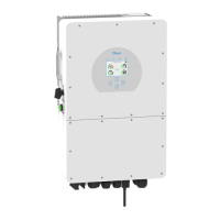
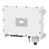
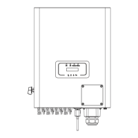
Identifies and labels the components and ports of the inverter.
Details the physical dimensions of the inverter and mounting bracket.
Lists the key technical specifications and capabilities of the hybrid inverter.
Illustrates a typical system configuration with the inverter and connected components.
Lists all the components included in the inverter package.
Provides precautions and guidelines for installing the inverter in a suitable location.
Details the required wire size and torque values for battery connections.
Explains the purpose and connections for various function ports on the inverter.
Shows how to connect the temperature sensor for lead-acid battery systems.
Guides on connecting the inverter to the grid and backup load terminals.
Explains how to connect PV modules, including cable size recommendations.
Outlines parameters for selecting suitable PV modules for the inverter.
Provides steps and safety hints for connecting PV module connectors.
Illustrates the wiring diagram for connecting Current Transformers (CTs).
Explains the requirement and method for grounding the inverter.
Refers to illustrations for configuring the Wi-Fi Plug.
Provides a detailed wiring diagram for a typical inverter application.
Shows a comprehensive wiring diagram for various connections.
Illustrates a system configuration that includes a diesel generator.
Shows a diagram for phase parallel connection, noted as under development.
Details the procedure for turning the inverter unit on and off.
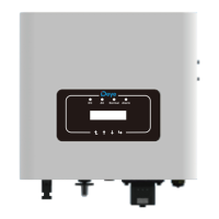
Explains the function of LED indicators and function buttons on the inverter.
Describes the information displayed on the inverter's main LCD screen.
Visualizes the navigation flow for accessing different menus and pages on the LCD.
Shows how to view solar, inverter, load, and grid data details.
Displays daily, monthly, and yearly power generation curves for solar and grid.
Provides access to various system configuration settings like Battery, Grid, and Work Mode.
Covers settings for Time Sync, Beep, Auto Dim, Factory Reset, and password protection.
Details settings for battery mode, capacity, charging, and discharge parameters.
Configures system operation modes like Selling First, Zero Export, and Grid Peak Shaving.
Allows configuration of grid mode, frequency, voltage, and other grid-related parameters.
Configures generator input, smart load output, and micro-inverter input settings.
Covers advanced features like Solar Arc Fault, Gen Peak-shaving, and meter selection.
Displays inverter ID, version information, and recorded alarm codes.
Illustrates a basic system setup without a generator.
Shows a system configuration including a generator.
Depicts a system configuration with a smart load.
Illustrates an AC coupled system setup.
Summarizes battery specifications like type, voltage range, and current limits.
Details PV input parameters like max power, voltage, MPPT range, and current.
Lists AC output ratings, including power, current, and frequency.
Provides efficiency ratings for the inverter, including MPPT efficiency.
Lists the integrated protection features of the inverter.
Provides general specifications like operating temperature, noise, weight, and dimensions.
Details the pin assignments for the RJ45 port used for BMS communication.
Details the pin assignments for the RJ45 port used for meter communication.
Provides the physical dimensions of the split-core current transformer.
| Model | SUN-8K-SG04LP3 |
|---|---|
| Type | Hybrid Inverter |
| Rated Output Power | 8000W |
| Max. Output Power | 8800W |
| Max. PV Input Power | 10400W |
| Number of MPPTs | 2 |
| Protection Class | IP65 |
| Nominal AC Output Power | 8000W |
| Max. AC Output Power | 8800W |
| Max. Input Current per MPPT | 13A |
| Battery Voltage Range | 40-60V |
| Max. Charging Current | 190A |
| Max. Discharging Current | 190A |
| Operating Temperature Range | -25°C to +60°C |
| Output Frequency | 50/60 Hz |
| Efficiency | 97.6% |
| Nominal AC Voltage | 230V |
| AC Voltage Range | 180-280V |
| MPPT Voltage Range | 200V-800V |
| Battery Type | Lithium-ion |
| Communication | RS485 |
| Output Voltage | 230V/400V |