
P
Patrick KiddJul 31, 2025
What does it mean when my Deye SUN300G3-EU-230 Inverter has a grid failure?
- TTracy MccallJul 31, 2025
A red LED blinking three times indicates a grid failure.
What does it mean when my Deye SUN300G3-EU-230 Inverter has a grid failure?
A red LED blinking three times indicates a grid failure.
General safety guidelines for installation and operation, including warnings and cautions.
Information regarding CE EMC compliance and measures to resolve radio frequency interference.
Explanation of symbols used in the manual, indicating hazards like electric shock and hot surfaces.
Explains how individual MPPT controls enhance energy harvest by optimizing each PV module.
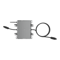
Highlights the distributed nature of microinverters, preventing single points of failure and operating at high temperatures.
Details the ease of installation, including wiring and data collection via WiFi.
Overview of microinverter capabilities, including single-phase and three-phase grid connection.
Lists optional components needed for installation, such as connectors and sealing caps.
Specifies the essential parts and tools that the user needs to provide for installation.
Instructions for installing the AC junction box and wiring the AC cable conductors.
Guidance on mounting microinverters to the PV racking system at designated locations.
Procedure for connecting microinverters in parallel, including AC connector interface details.
Final steps involve installing AC cable end caps and connecting microinverters to PV modules.
Steps to operate the microinverter PV system, including turning on AC breakers and waiting for power generation.
Explains LED indicators for operation status and how microinverters transmit performance data.
Details LED status indications and error reporting for startup and operational issues.
Provides methods to diagnose and resolve issues with non-operating microinverters.
Step-by-step guide for safely disconnecting and replacing a faulty microinverter.
Technical specifications for 300W, 500W, and 600W microinverters, including input, output, and mechanical data.
Technical specifications for 800W and 1000W microinverters, covering input, output, and mechanical details.
Technical specifications for 1300W to 2000W microinverters, including performance and physical data.
Illustrates the three-phase wiring configuration for microinverter systems.
Demonstrates the single-phase wiring configuration for microinverter systems.
Information on accessing monitoring platforms via web addresses and mobile apps, including QR codes.
| Model | SUN300G3-EU-230 |
|---|---|
| Type | Microinverter |
| Rated Output Power | 300W |
| Max. DC Input Voltage | 60V |
| MPPT Voltage Range | 25-50V |
| Output Voltage | 230V |
| Nominal AC Voltage | 230V |
| Output Frequency | 50/60Hz |
| Nominal AC Frequency | 50/60Hz |
| Power Factor | >0.99 |
| Total Harmonic Distortion (THD) | <3% |
| MPPT Efficiency | 99.5% |
| MPPT Range | 25-50V |
| Max PV Input Voltage | 60V |
| Enclosure Rating | IP67 |
| Cooling | Natural Convection |
| AC Voltage Range | 180-280 V |
| Operating Temperature Range | -40~+65°C |
| Operating Temperature | -40~+65°C |
| Protection | Over Temperature |
| Communication | WiFi, RS485 |
| Max. Units per Branch | 15 |