Do you have a question about the DFRobot FIREBEETLE BOARD-ESP32 and is the answer not in the manual?
Overview of the FireBeetle product line, designed for IoT.
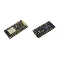
Details about the ESP32-based FireBeetle board and its features.
Technical specifications and hardware features of the ESP32 board.
Detailed physical dimensions and electrical specifications of the board.
Guide to setting up the Arduino IDE for the FireBeetle Board-ESP32.
Instructions for downloading and installing the Arduino IDE software.
How to change the language within the Arduino IDE interface.
Adding the ESP32 board support package to Arduino IDE.
Connecting the board to a PC and verifying its recognition.
Basic programming workflow and interface overview in Arduino IDE.
Process of compiling and uploading code to the FireBeetle-ESP32.
Demonstrates using the serial port for data communication.
Controlling LED brightness via PWM for a breathing effect.
Reading analog signals using the Analog-to-Digital Converter.
Interfacing with devices using the I2C communication protocol.
Utilizing the SPI bus for sensor data communication.
Reading data from the integrated Hall effect sensor.
Generating analog output signals using the Digital-to-Analog Converter.
Using the capacitive touch sensors on the board.
Implementing low-power deep sleep modes for power management.
| Brand | DFRobot |
|---|---|
| Model | FIREBEETLE BOARD-ESP32 |
| Category | Microcontrollers |
| Language | English |