22
BASIC CONFIGURATION (BASE SETUP)
1.1
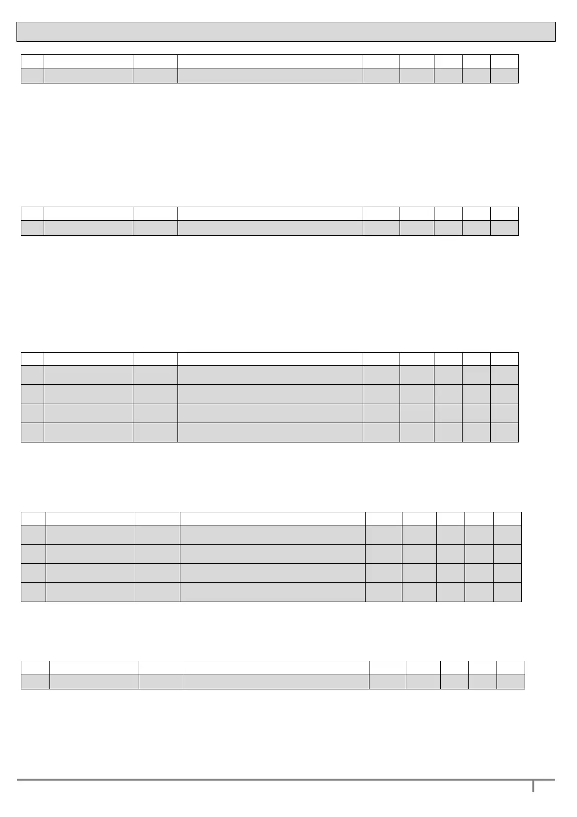
PRESSURE SET 1 P1 Working pressure 1 bar 3.5 0,5 * 0.1
* the maximum set pressure depends from the connected pressure sensor full scale
P1 is the MAIN operating pressure; the DGBOX control will drive the connected pumps to
keep the system at the selected pressure.
The required pressure must be set in agreement with pump performance.
In the case of operation without flow sensor (see parameter 3.13 - FLOW SENSOR), together
with the operating pressure P1, the parameter OFF FREQ SP1 will also have to be set; this
sets the off frequency (see parameter 2.18 – OFF FREQ SP1).
1.2
PRESSURE SET 2 P2 Working pressure 2 bar 2.5 1.0 * 0.1
* the maximum set pressure depends from the connected pressure sensor full scale
P2 is the second work pressure. Operation with the second work pressure is started by the external
control connected to the digital input IN1 or IN2 (see parameters 3.5/3.6).
The required pressure must be set in accord with the pump performance.
In the case of operation without flow sensor (see parameter 3.13 - FLOW SENSOR), together with
the second work pressure P2, the parameter OFF FREQ SP2 must also be set. This sets the stop
frequency (see parameter 2.19 – OFF FREQ SP2).
1.3
PUMP 1 CURRENT
CU1 Nominal current pump n°1 A
*
*
*
0.1
1.5
PUMP 2 CURRENT
CU2 Nominal current pump n°2 A * * * 0.1
1.7
PUMP 3 CURRENT
CU3 Nominal current pump n°3 A * * * 0.1
1.9
PUMP 4 CURRENT
CU4 Nominal current pump n°4 A * * * 0.1
Rated current of the pump motor. This figure determines the ammeter protection of the
motor pump and must coincide with the motor plate current.
*
the values vary according to the power of the inverter taken into consideration.
1.4
PUMP 1 ROTATION
RO1 Rotation direction of pump n° 1 - CW CW ACW
-
1.6
PUMP 2 ROTATION
RO2 Rotation direction of pump n° 2 - CW CW ACW
-
1.8
PUMP 3 ROTATION
RO3 Rotation direction of pump n° 3 - CW CW ACW
-
1.10
PUMP 4 ROTATION
RO4 Rotation direction of pump n° 4 - CW CW ACW
-
Direction of rotation of pump 1: permits electronically changing the direction of rotation
without having to switch over the wires on the terminal board.
1.11 SERIAL -FIRMW -- Serial number and firmware version - - - - -
DGBOX serial number and firmware version of the control board.
 Loading...