4
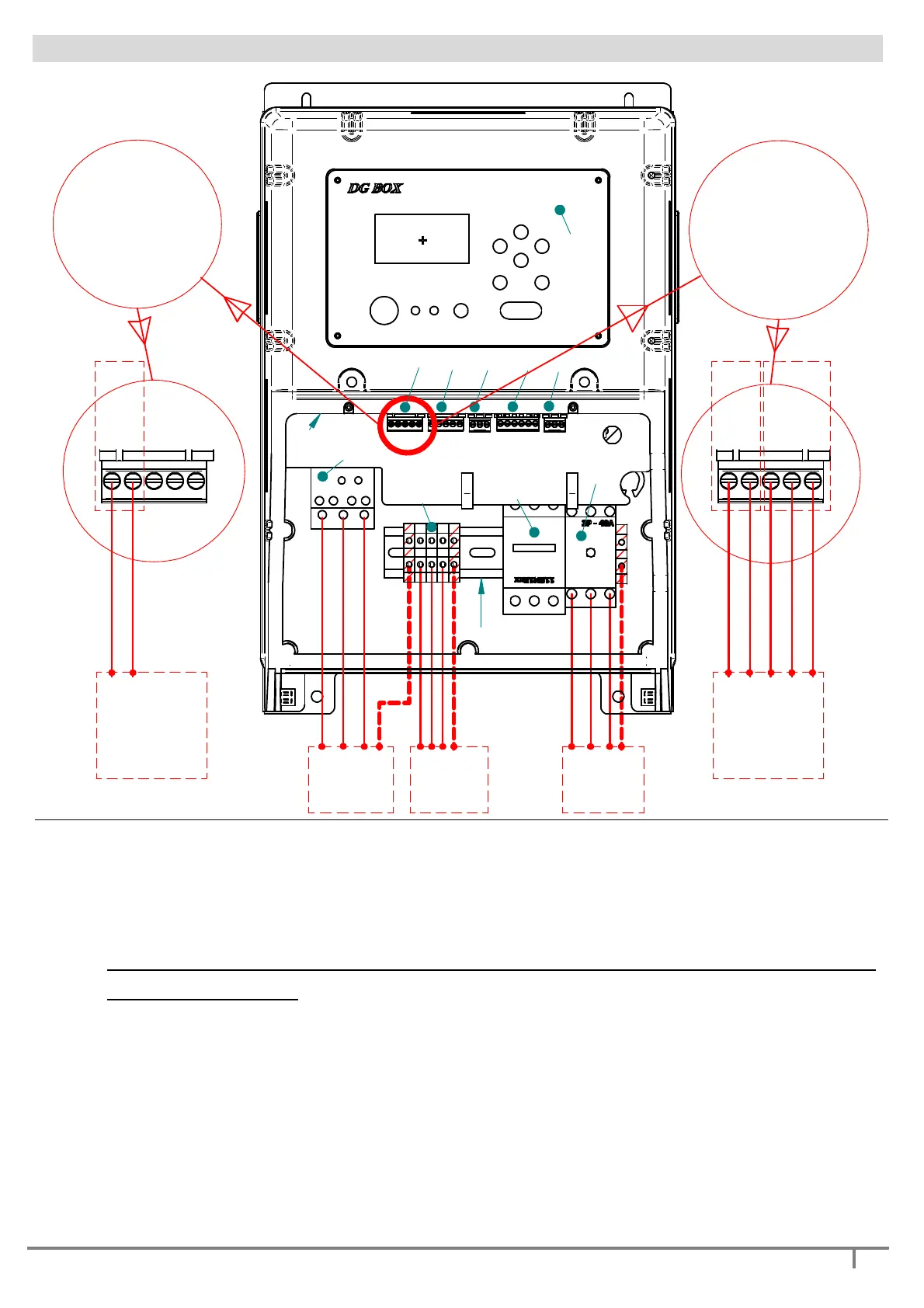
DESCRIPTION OF THE MAIN COMPONENTS
LINE
PUMP 1
PUMP 2
U V W GND
R S T GND
U V W GND
+Vdc+Vdc
4-20 mA
flow C
flow NO
GND
brown
black
grey
white
blue
TEEVALVE
1
2
3
4
5
6
7
8
9
10
11
12
+Vdc+Vdc
4-20 mA
flow C
flow NO
GND
PIN 1 +
PIN 2 -
DANFOSS
PRESSURE SENSOR
( DANFOSS )
PRESSURE SENSOR
+
FLOW SENSOR
( TEEVALVE )
1. Disconnection switch
2. Thermal magnetic switch / fuse-carrier module
3. Inverter 1 output terminal board
4. contactor with thermal motor protection (fixed speed pump)
ATTENTION: set the protection of the thermal relay to the rated current of the pump
2 (fixed speed pump)
5. input signal terminal board 1 (analogue1 + flow signal 1)
6. input signal terminal board 2 (analogue2 + flow signal 2)
7. digital input signal terminal board IN1 and IN2
8. digital output signal terminal board OUTPUT1 and OUTPUT2
9. signal terminal board RS 485
10. USB port
11. keyboard / display screen
12. terminal clamps fixing bar (DIN standard)