5
INPUT / OUTPUT SIGNAL CONNECTIONS
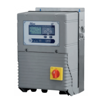
INPUT SIGNAL CONNECTIONS
IN 2
4-20 mA
Flow C.
Flow N.O.
0 V
+ Vdc
4-20 mA
Flow C.
Flow N.O.
0 V
PRESS/FLOW 1
RS485
+ Vdc
2 - C
+ Vdc
0 V
IN 1
PRESS/FLOW 2
2 - N.O.
2 - N.C.
D +
D -
1 - C
1 - N.C.
1 - N.O.
INPUT
OUTPUT
1
2
- permits connecting two input signals of the
clean-contact type
- see param. INPUT 1 CONFIG
- see param. INPUT 2 CONFIG
- If the contact of the sensor (eg. a level probe) is
open, the operation is inhibited
- Operating current is 5 mA for each input
- Max capacity from Vdc is 100 mA.
-
The power voltage supply (+ 24 Vdc) CANNOT
be used to supply external devices.
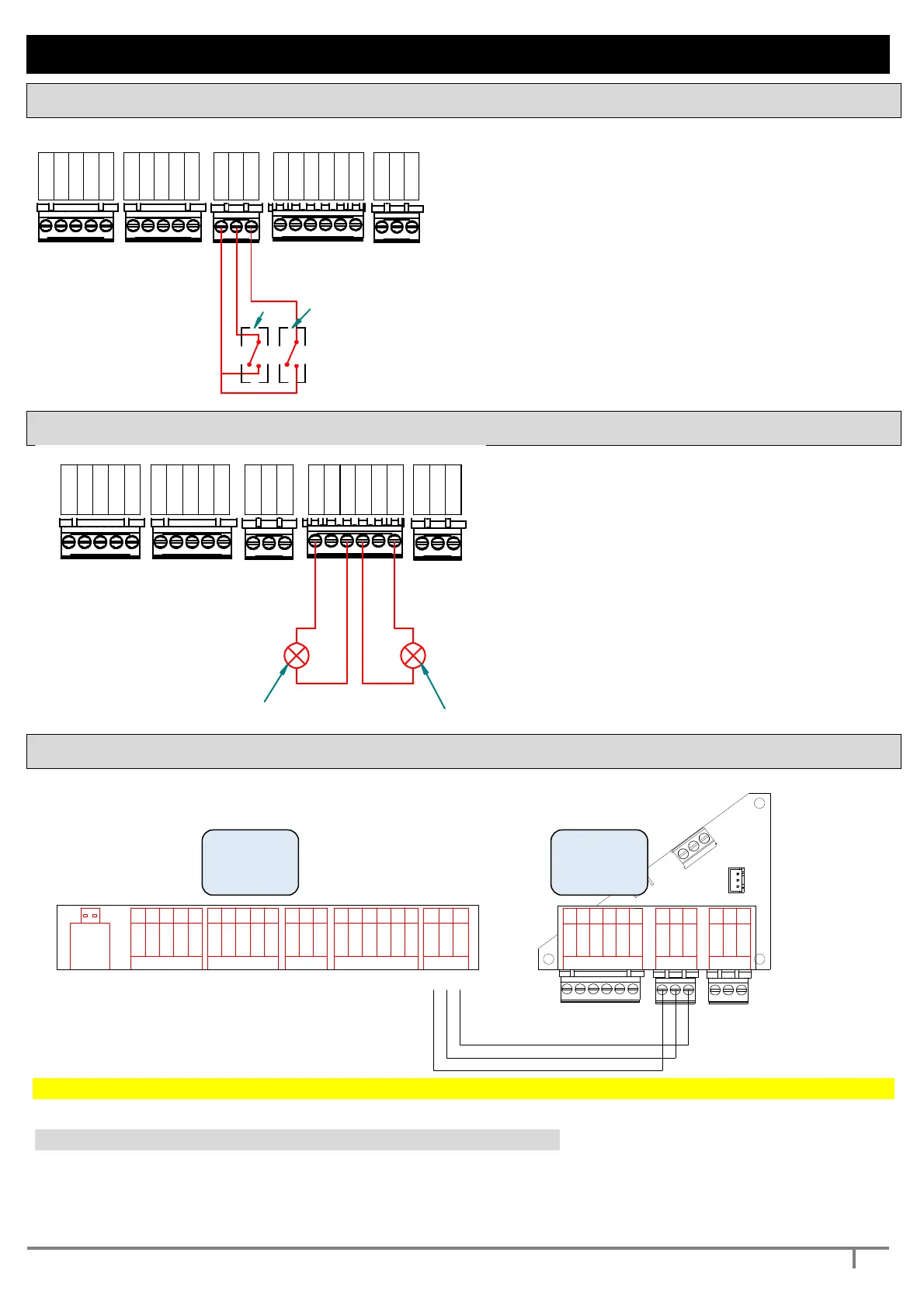
OUTPUT SIGNAL CONNECTIONS
IN 2
4-20 mA
Flow C.
Flow N.O.
0 V
+ Vdc
4-20 mA
Flow C.
Flow N.O.
0 V
+ Vdc
2 - C
+ Vdc
0 V
IN 1
2 - N.O.
2 - N.C.
D +
D -
1 - C
1 - N.C.
1 - N.O.
max 5A
250 V
max 5A
250 V
2
- 2 relay outputs are available
- These can be connected both with NO
logic and with NC logic
- see. param. OUTPUT 1 CONFIG
- see. param. OUTPUT 2 CONFIG
- The max load which can be connected is
2 A at 250 Vac
-
the cable must have 2 leads and a
minimum cross-section of 0.5 square
mm
MASTER – SLAVE CONNECTIONS
permits connection and communication with external devices by means of standard RS485
S
1
S3
(
V
a
c
)
C
S
3
(
V
a
c
)
j5
j
4
+
2
4
V
d
c
S
2
G
n
d
S3 (Vac)
I/O AUXILIARY
Gnd
D -
D+
+ 24Vdc
S1
Gnd
S2
54
32
1
32
1
CS3 (Vac)
1
2 3
D+
D -
Gnd
6
Rs 485 OUT
Rs 485 IN
1 2 36543213211 2 3 4 5
PRESS / FLOW 1
54321
USB
+ Vdc
Flow N.O.
4-20 ma
Flow C.
+ Vdc
+ Vdc
In 1
In 2
1 - C
1 - N.C.
D+
D -
Gnd
2 - C
2 - N.C
2 - N.O.
PRESS / FLOW 2 INPUT OUTPUT Rs 485
Gnd
4-20 ma
Flow C.
Flow N.O.
Gnd
1 - N.O.
To operate the system MASTER / SLAVE is necessary to address the pump 2 to inverter SLAVE.
to address the pump 2 to inverter SLAVE set the parameter 3.2 PUMP 2 CONFIG = 3 (EXT. INV. 2)
The other parameters are set in SELF-LEARNING or they can be set manually
1.5 PUMP 2 CURRENT (SLAVE pump protection) and 1.6 PUMP 2 ROTATION
2.8 MIN POWERF2 = minimum power factor of the pump 2 for protection against dry running
2.11 POWERF TIME = enables protection against dry running for COSFI.
MASTER
SLAVE