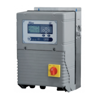
EasyManua.ls Logo

DGFLOW DGB MV 30 User Manual

DGFLOW DGB MV 30
40 pages
To Next Page IconTo Next Page
Page #1 background imageLoading...
Page #1 background image
1
DGBOX
rev. 1602
Inverter electronic control panels
for single pumps or pumping units
OPERATOR’S AND MAINTENANCE MANUAL
Model V in V out A P (kW) P (HP)
DGB MV 30
3 ~ 400V 3 ~ 400V
8 3 4
DGB MV 55
3 ~ 400V 3 ~ 400V
14 5,5 7,5
DGB MV 75
3 ~ 400V 3 ~ 400V
18 7,5 10
DGB MVF 30
3 ~ 400V 3 ~ 400V
8 + 8 3 + 3 4 + 4
DGB MVF 55
3 ~ 400V 3 ~ 400V
14 + 14 5,5 + 5,5 7,5 + 7,5
DGB MVF 75
3 ~ 400V 3 ~ 400V
18 + 18 7,5 + 7,5 10 + 10
DGB MW 30
3 ~ 400V 3 ~ 400V
8 + 8 3 + 3 4 + 4
DGB SV 30
3 ~ 400V 3 ~ 400V
8 3 4
DGB SV 55
3 ~ 400V 3 ~ 400V
14 5,5 7,5
DGB SV 75
3 ~ 400V 3 ~ 400V
18 7,5 10
10154507A .03 - 170530
EN

Questions and Answers:

DGFLOW DGB MV 30 Specifications

General IconGeneral
BrandDGFLOW
ModelDGB MV 30
CategoryControl Panel
LanguageEnglish

Summary

SAFETY STANDARDS

INSTALLATION

DESCRIPTION OF THE MAIN COMPONENTS

INPUT / OUTPUT SIGNAL CONNECTIONS

INPUT SIGNAL CONNECTIONS

Details on connecting input signals for sensors and control.

OUTPUT SIGNAL CONNECTIONS

Details on connecting output signals for relays and indicators.

MASTER – SLAVE CONNECTIONS

STARTING UP

SELF-LEARNING CONFIGURATION

MAIN MENU and PARAMETER MENU

BASE SETUP

Sets up basic operational parameters like working pressure and pump current.

ADVANCED CONFIGURATION (ADV SETUP)

Configures advanced parameters for optimizing plant engineering situations.

HARDWARE CONFIGURATION (HARDWARE SETUP)

Sets up signal inputs and outputs on the control board.

SETTING THE PARAMETERS REQUIRED FOR OPERATION

CHECKING THE DIRECTION OF THE MOTOR (PUMP 1 ROTATION)

PARAMETER CONFIGURATION AND CHECKS

CHECKING ELECTRIC MOTOR FREQUENCY

Verify MOTOR FREQ parameter matches the motor plate frequency.

CHECKING MAXIMUM OPERATING FREQUENCY

Verify MAX FREQ parameter matches motor plate frequency.

SETTING OFF FREQUENCY (SP1)

Set the shutdown frequency for operation without a flow sensor.

SETTING PRESSURE SENSOR FULL-SCALE

Enter the full-scale value for connected pressure sensors.

SETTING THE FLOW SENSOR

Configure the flow sensor parameter.

CONTROL OF DRY RUNNING APPLICATIONS WITHOUT FLOW SENSOR

TEST

ALARMS

PART 2 – USER'S MANUAL

GENERAL REMARKS

Overview of DGBOX control panels for single and multi-pump units.

CONTROL PANEL

EMERGENCY ELECTRONIC BOARD

TECHNICAL DATA and WORKING LIMITS

DIMENSIONS and WEIGHTS

MULTI-PUMPS SYSTEMS

PRODUCT MODELS AND IDENTIFICATION CODES

SURGE TANK

SAFETY PRESSURE SWITCH

OPERATING MODES

CONFIGURATION

Access and modify working parameters, including base, advanced, hardware setups, and maintenance.

TEST

Perform manual functional tests on variable-speed and fixed-speed pumps.

WORK

Normal operating mode, controlling parameters and displaying alarms.

OUT OF SERVICE

Manually stop the system or single pumps for maintenance or configuration.

UPDATE

Perform DGBOX maintenance or software update operations via USB.

TROUBLESHOOTING

WARRANTY

DISPOSAL

DECLARATION OF CONFORMITY

Related product manuals