10
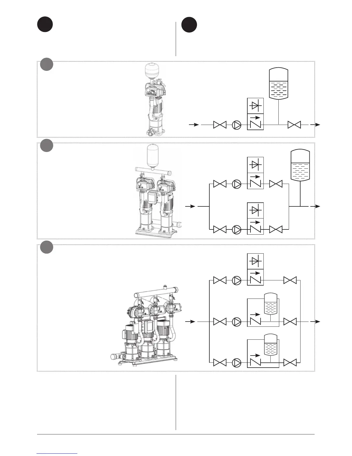
Schemi tipici di installazione dell’inverter: Typical inverter installation layouts:
• su pompa singola, che
lavora in modulazione dalla
frequenza minima alla massima
programmate.
• on single pump, which
works in modulating mode at
minimum and maximum pro-
grammed frequency
• su gruppo a due pompe,
in parallelo: il gruppo lavora in
modulazione dalla frequenza
minima alla massima program-
mate.
• on unit with two pumps,
in parallel: the unit works in
modulating mode from the mini-
mum to maximum programmed
frequency.
1. Ingresso
2. Valvola di intercettazione
3. Pompa
4. Inverter (valvola di non ritorno incorporata)
5. Vaso di espansione a membrana
6. Controllo Slave con accumulo e valvola di non
ritorno incorporate.
1. Input
2. Cut-off valve
3. Pump
4. Inverter (built-in non-return valve)
5. Expansion vessel with diaphragm
6. Slave control with storage tank and non-return
valve incorporated.
IT
CARATTERISTICHE
DELL’IMPIANTO
SYSTEM FEATURES
EN
1
2 23
4
5
1
2 23
4
2 23
4
5
1
2 23
4
2
2
2
2
3
3
6
6
• su gruppo a tre pompe: la pompa con
inverter (master) lavora in modulazione, e
raggiunta la frequenza massima attiva in
sequenza le due pompe slave, che lavorano
in modo ON/OFF.
• on unit with three pumps:
the pump with inverter
(master) works in modulating
mode and on reaching the
maximum frequency
activates the two slave
pumps in sequence,
which work in ON/OFF
mode.
C
B
A