31
Wiring and connections
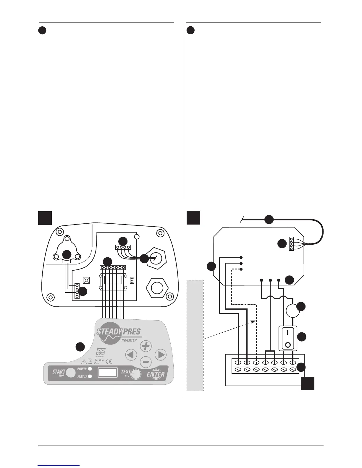
The inverter is composed of 3 boards:
A - Control board
B - Power board
C - power supply and motor output board.
The 3 boards and relative connections are repre-
sented in the layouts below.
Control board: situated under the front part of
the inverter (Position A), is the inverter interface
with the operator, memorises the functioning
parameters and system settings.
The control board has a keyboard (1) and display
from which it is possible to monitor the functioning
conditions of the inverter and modify settings. The
keyboard is connected to the board via a at cable
and 7-pole connector (2).
The pressure sensor (3) is connected to the board
via the 4-pole connector (4).
The communication between the control board
and power board is the RS232 serial type.
The connection between the two serial ports (6)
and (7) is via 4-pole cable (5).
Power board: situated in the rear of the inverter
(position B), it contains the inverter power com-
ponents
The board is connected to the electric mains via
cables welded to the terminals L1, G1, N1 (10)
The cut-off of the power supply and the protection
EN
IT
Manutenzione
Cablaggi e connessioni
L’inverter si compone di 3 schede:
A - Scheda di controllo
B - scheda di potenza
C - scheda di alimentazione e uscita motore.
Negli schemi riportati di seguito vengono rappre-
sentate le 3 schede ed i relativi collegamenti.
Scheda di controllo: situata sotto la parte fronta-
le dell’inverter (Posizione A) costituisce l’interfaccia
dell’inverter con l’operatore, memorizza i parametri
di funzionamento e i settaggi di impianto.
La scheda di controllo è dotata di tastiera (1) e
display da cui si possono monitorare le condi-
zioni di funzionamento dell’inverter e modicarne
i settaggi; la tastiera viene collegata alla scheda
mediante cavo at e connettore a 7 poli (2).
Il sensore di pressione (3) viene collegato alla
scheda mediante connettore a 4 poli (4).
La comunicazione tra scheda di controllo e sche-
da di potenza è di tipo seriale RS232.
Il collegamento tra le due porte seriali (6) e (7)
viene effettuato mediante cavo a 4 poli (5).
Scheda di potenza: situata nella parte posteriore
dell’inverter (Posizione B) contiene i componenti di
potenza dell’inverter
La scheda è collegata alla rete elettrica mediante i
cavi saldati ai terminali L1,G1,N1 (10)
L’interruzione dell’alimentazione e la protezione da
5
6
3
4
2
1
A
V W
7
8
9
11
10
12
N
L1G1N1
U
V
W
U GND L
5
B
C
Presente solo nella versione trifase.
Present only in the three-phase version.
Maintenance