13
Installazione Installation
EN
IT
no a 30m, dovrà essere di almeno 2,5mm2.
Il collegamento alla linea di alimentazione andrà
effettuato sui morsetti L ,N e GND dell’inverter
(vedi gura).
• Collegamento all’elettropompa.
Versione con Inverter alimentato in monofase
con output trifase.
Controllare che la corrente
nominale assorbita dal motore
sia compatibile con i dati di
targa dell’inverter. La tensione
di alimentazione del motore
dell’elettropompa installata
deve essere 230V Trifase.
Il Cavo di connessione tra
inverter ed elettropompa dovrà
essere a 4 conduttori (3 fasi
+ Terra), la sezione del Cavo
da utilizzare, dovrà essere di
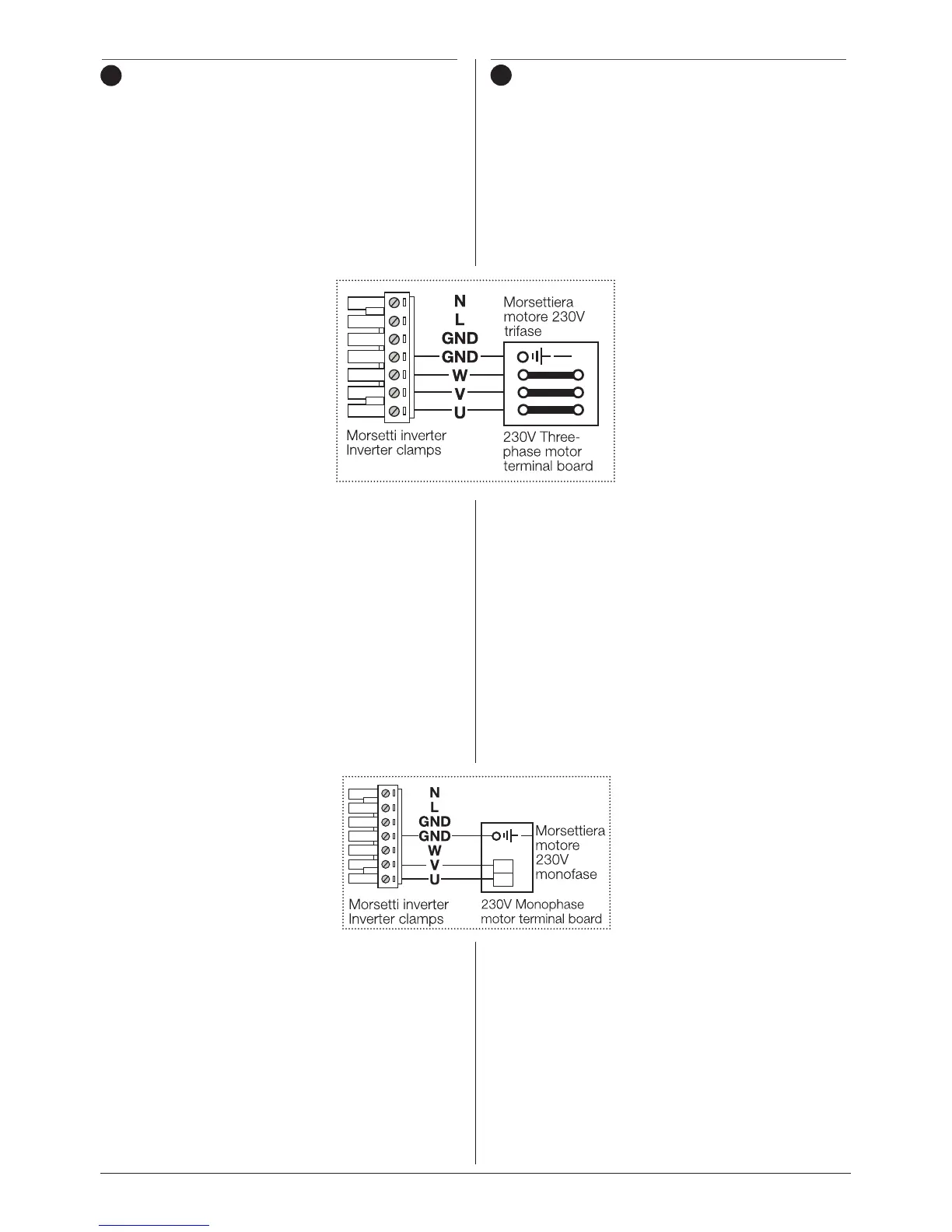
almeno 1,5mm2. Il collegamento tra inverter e mo-
tore andrà effettuato sui morsetti U, V, W e GND
dell’inverter secondo lo schema sotto riportato. Il
collegamento tra motore e inverter dovrà rispettare
la normativa sulla compatibilità EMC.
• Collegamento all’elettropompa.
Versione con Inverter alimentato in monofase
con output in monofase.
Controllare che la corrente nominale assorbita dal
motore sia compatibile con i dati di targa dell’in-
verter. La tensione di alimentazione del motore
dell’elettropompa installata deve essere 230V
Monofase. Il Cavo di connessio-
ne tra inverter ed elettropompa
dovrà essere a 3 conduttori (2
fasi + Terra), la sezione del Cavo
da utilizzare, dovrà essere di
almeno 2,5mm2.
Il collegamento tra inverter e
motore andrà effettuato sui
morsetti U ,V e GND dell’inver-
ter secondo lo schema sotto
riportato.
Il collegamento tra inverter e motore andrà
effettuato sui morsetti U, V e GND dell’inverter se-
condo lo schema sotto riportato. Il collegamento
tra motore e inverter dovrà rispettare la normativa
sulla compatibilità EMC.
The connection to the power supply line will be
performed on the L, N and GND clamps of the
inverter (see gure).
• Connection to the electric pump.
Version with inverter powered in single-phase
with three-phase output.
Check that the nominal current
absorbed by the motor is
compatible with the inverter
plate data.
The power supply voltage of
the electric motor, must be
230V three-phase. The con-
nection cable between inverter
and electric pump must be with
4 wires (3 phases + ground),
the section of the cable to be
used must be at least 1.5mm2.
The connection between the inverter and motor
will be performed on the U, V, W and GND clamps
of the inverter, according to the layout below. The
connection between motor and inverter must
respect the Standard regarding EMC.
• Connection to the electric pump.
Version with inverter powered in single-phase
with single-phase output.
Check that the nominal current absorbed by the
motor is compatible with the inverter plate data.
The power supply voltage of the electric motor,
must be 230V Single-phase. The connection cable
between inverter and electric
pump must be with 3 wires (2
phases + ground), the section
of the cable to be used must be
at least 2.5mm2.
The connection between the
inverter and motor will be per-
formed on the U, V and GND
clamps of the inverter, accor-
ding to the layout below. The connection between
motor and inverter must respect the Standard
regarding EMC.
L
N