EasyManua.ls Logo

Dhollandia DH-VOU 16 K2K9 User Manual

Dhollandia DH-VOU 16 K2K9
48 pages
To Next Page IconTo Next Page
Page #1 background imageLoading...
Page #1 background image
Order ref: xxx Doc: FIT_US installation manual VOU K2K9_US EN_2022 Rev: 1 Date: SEPTEMBER 1, 2023
DH-VOU 16 K2K9
INSTALLATION MANUAL
Read the manual in its entirety before operating the liftgate
Keep this manual in the vehicle cab, as reference for the driver and liftgate operator
Manufacturer:
DHOLLANDIA US, L.L.C.
E-mail : Technical.US@dhollandia.com
270 Southridge Parkway
Bessemer City North Carolina, 28016
website : www.dhollandia.com

Table of Contents

Question and Answer IconNeed help?

Do you have a question about the Dhollandia DH-VOU 16 K2K9 and is the answer not in the manual?

Dhollandia DH-VOU 16 K2K9 Specifications

General IconGeneral
BrandDhollandia
ModelDH-VOU 16 K2K9
CategoryLifting Systems
LanguageEnglish

Summary

1 UNDERSTANDING SAFETY AND WARNING SIGNS

2 INTRODUCTION, CONTACT INFO AND DISCLAIMERS

DISCLAIMERS

Important legal notices and limitations of liability for DHOLLANDIA.

3 SAFETY PRECAUTIONS FOR OPERATION

4 SAFETY PRECAUTIONS FOR INSTALLATION

5 LIFTGATE TERMINOLOGY

5.1 DH-VOU K2K9 LIFTGATE TERMINOLOGY

Specific terminology for the DH-VOU K2K9 liftgate model.

5.2 INSTALLATION PARAMETERS TERMINOLOGY

Defines installation dimensions and measurement parameters for liftgate fitting.

5.3 GETTING STARTED

Initial steps and considerations before beginning the liftgate installation.

6 INSTALLATION DIMENSIONS AND GUIDELINES

6.1 INSTALLATION DIMENSIONS

Specifies key dimensions required for liftgate mounting and fitment.

6.2 INSTALLATION RESOURCES

Information on where to find additional installation resources and support.

6.3 IMPORTANT GUIDELINES

General installation advice, including risk assessment and compliance.

6.4 ADDITIONAL GUIDELINES FOR LIFTGATES TRAVELING ABOVE VEHICLE FLOOR LEVEL

Specific safety and functional guidelines for liftgates operating above vehicle floor.

6.4.1 Guard rails

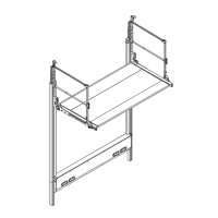
Requirements and considerations for fitting guard rails to prevent falls.

6.4.2 Audible and visible alarm

Guidelines on installing audible and visible alarms for safety.

7 MOUNTING OF THE LIFT FRAME (PREMOUNTED PLATFORM)

7.1 HANDLING

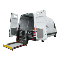
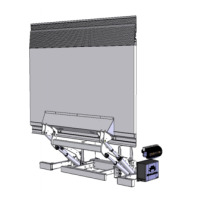
Safe procedures for handling and lifting the lift frame components.

7.2 WELDED INSTALLATION

Detailed steps and precautions for welding the liftgate components.

7.3 BOLT-ON INSTALLATION

Procedures for installing the liftgate using bolted connections.

7.3.1 Position of the drill holes

Guidance on marking and drilling holes for bolt-on installation.

7.3.2 Mounting of the lift frame

Steps for securing the lift frame using bolts and ensuring proper alignment.

8 GENERAL REMARKS

8.1 POWER PACK INSTALLATION

Instructions for mounting the power pack unit onto the vehicle chassis.

8.2 TRIMMING OF THE LIFT COLUMNS

Procedures for trimming lift columns to ensure proper ground clearance.

9 INSTALLATION OF ELECTRICAL CONTROLS

9.1 INSTALLATION OF THE CONTROL SWITCH (OAE015.PR – E0832.B)

Detailed guide for installing the primary toggle control switch.

9.2 INSTALLATION OF THE CABIN SWITCH (OAE510.15 – E0393.S.15)

Instructions for installing the cabin-mounted control switch.

9.3 INSTALLATION OF EXTRA CONTROLS – 2 BUTTON REMOTE CONTROL (OAE001 – E0787.2.M.S)

Guide for installing an optional 2-button remote control system.

10 ELECTRICAL INSTALLATION

10.1 INSTALLATION OF THE (+) BATTERY CABLE AND (-) GROUND CABLE

Procedures for connecting the main battery and ground cables to the liftgate.

10.2 LIFTGATE SCHEMATIC

Provides the general hydraulic and electric schematic for the liftgate.

11 PUTTING THE LIFTGATE INTO SERVICE

12 PLATFORM ORIENTATION

12.1 PLATFORM PITCH ADJUSTMENT

Steps to adjust the platform pitch for level ground alignment.

12.2 PLATFORM LOCK ADJUSTMENT FOR OPEN / CLOSED POSITION

How to adjust the platform lock mechanism for opening and closing.

12.3 PLATFORM FOLD / UNFOLD ASSIST

Guidance on adjusting or servicing the platform fold/unfold assist mechanism.

12.4 UPPER END STOPS

Adjusting the upper end stops for proper platform parallelism.

13 LUBRICATION INSTRUCTIONS

14 QUALITY CONTROL AND PDI

CHECKLIST FOR THE PRE-DELIVERY-INSPECTION (PDI) TEST

A checklist for performing the final quality inspection before delivery.

15 DECALS

15.1 USE OF THE ‘WARNING. LIFTGATE OUT OF SERVICE. DO NOT ATTEMPT TO OPERATE' SIGN

Proper placement and use of the 'out of service' warning decal.

16 APPENDIX

16.1 MEANING OF THE SAFETY AND WARNING SIGNS

Detailed explanation of various safety, mandatory action, and prohibition signs.

16.2 PRESCRIBED TORQUE VALUES FOR BOLTS AND NUTS

Table of specified torque values for different bolt types and classes.

16.3 ELECTRIC AND HYDRAULIC REQUIREMENTS

Recommended cable sizes and battery/generator requirements for the system.

16.4 SAFE OPERATOR POSITION ON THE PLATFORM

Guidelines for safe operator positioning to avoid hazards on the platform.

16.5 END NOTE

Final closing remarks and contact information for additional support.

16.6 BASIC WIRING DIAGRAMS

References for obtaining general hydraulic and electric wiring diagrams.

16.7 CHECKLIST FOR PREVENTATIVE MAINTENANCE AND REPAIR

Checklist for performing routine maintenance and repair tasks.

Related product manuals