9 INSTALLATION OF ELECTRICAL CONTROLS
9.1 INSTALLATION OF THE CONTROL SWITCH (OAE015.PR – E0832.B)
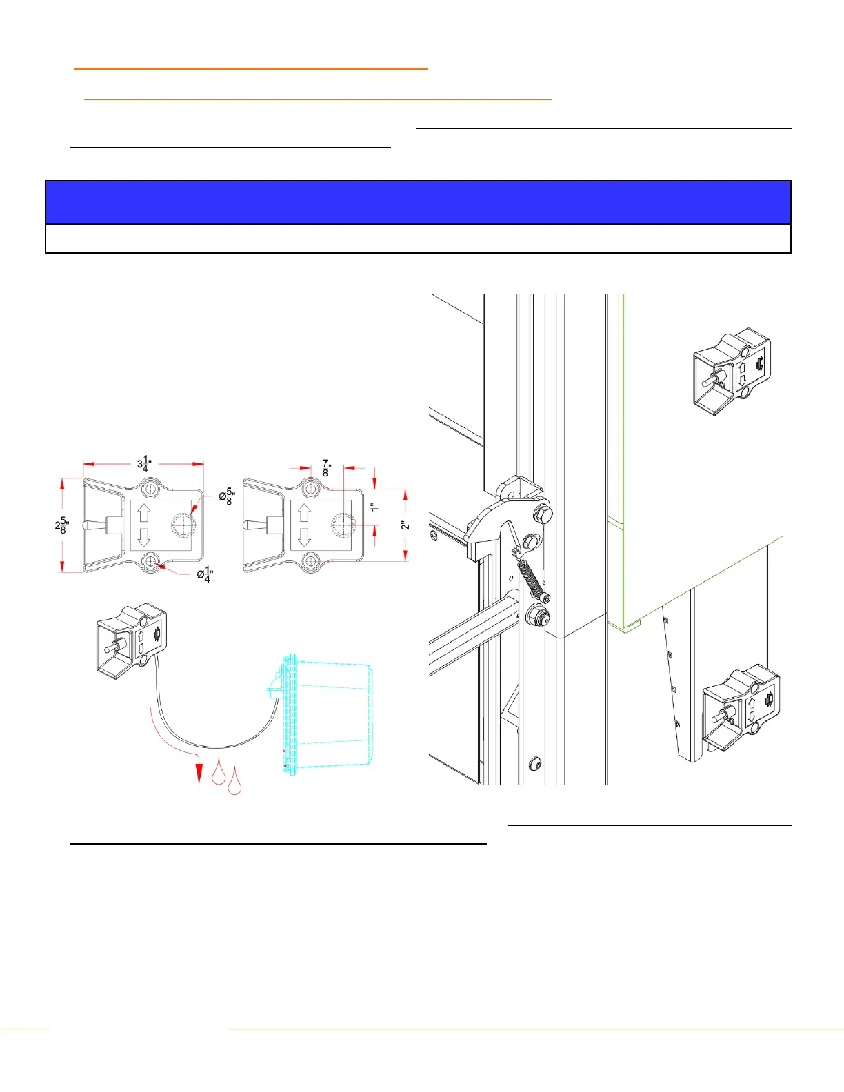
• Mount the toggle switch in a position that allows the operator to work from a safe standing area at the side of the liftgate, outside
reach of the platform and other moving parts of the lift.
• Mount it in a location that is accessible from the ground.
• In order to avoid water ingress and electrical malfunction, NEVER mount the toggle switch facing upwards.
• Measure the holes on the control unit itself or use the template
to drill the screw holes, and the passage for the electrical
cable.
• Use #10-32 – 1 inch (4.3mm) self-tapping screws to mount
the control switch.
• Route the electrical cable to the pump unit. Position, fasten
and protect it in such a way that it cannot be damaged by the
moving parts of the liftgate or other vehicle components.
• Feed the electrical cable through the rubber cover at the rear of the pump unit. Check and make sure the rubber cover properly
seals and protects the inside of the pump unit, after passing the cable.
• Prevent ingress of water into the pump unit and control boxes if applicable.
• Route and secure cables downward, forming a “drip loop” as they exit the pump unit.
• Connect the wires of the cable to the connection points in the pump unit as per wiring diagram below.
 Loading...