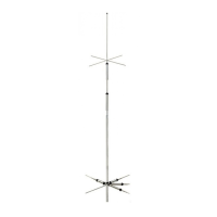
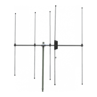
BROADBAND HF DIPOLE ANTENNA
COMPACT SIZE
WD330S
OPERATING INSTRUCTIONS
Thank you for purchasing the Diamond HF Dipole
Antenna. Before using the antenna, please read care-
fully these OPERATING INSTRUCTIONS to operate
properly. SAVE THESE INSTRUCTIONS.
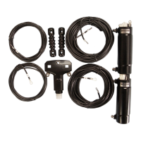
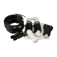
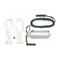
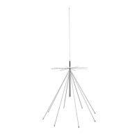
The WD330S broadband dipole antenna is designed to
provide optimum performance over a wide frequency
range, and it is very easy to assemble.
The usual requirements for multiple antennas or an anten-
na tunes between the transceivers and antenna are elimi-
nated by the unique broadband design.
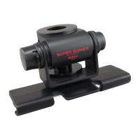
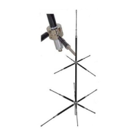
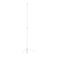
Installation
Refer to the drawings on the opposite side of this sheet for
suggested installations. For best performance, the antenna
should be installed with the radiating elements in a horizon-
tal ("Flat Top") configuration, and as high as possible.
Theoretically, the directions of maximum radiation and
reception are at right angles to the radiating elements, and
this should be considered when planning installation.
However, this radiation pattern is based on an ideal anten-
na in free space, and may be considerably different in a
practical situation near the ground and adjacent to other
structures and power lines; some experimentation with
mounting and orientation can significantly improve perfor-
mance, Proximity of ground and nearby structures may
also affect the feedpoint impedance of the antenna, so
rearrangement of the antenna could be required to achieve
a good VSWR.
Performance Verification
The impedance match of the antenna should be verified
prior to using the antenna with a transmitter, or if there is
doubt about performance.
Install a directional wattmeter between the antenna and the
DIAMOND
ANTENNA
transceiver. Key the transmitters with a steady carries and
adjust the forward output power for approximately 20 watts.
Switch the wattmeter to read reflected power measures in
excess of 5 watts, the problem should be corrected before
attempting to use the antenna.
Troubleshooting
First check for broken, shorted or twisted wires, ground
leads or faulty connections in the feedline and connectors.
Then consider reconfiguring or reorienting the antenna rel-
ative to the ground or nearby structures.
Specifications
Frequency range
Max.Power range
Input impedance
VSWR(typical)
Length
: 2—28.6MHz
: 150 W PEP
: 50 Q
: from 2-18 MHz,
3:1 above 18 MHz
: 10 meters
DAI-ICHI DENPA KOGYO CO., LTD. 445-1 Konakai Nakadori Kawagoe, Saitama 350-0022 Japan