Do you have a question about the Diamond Antenna W-8010 and is the answer not in the manual?
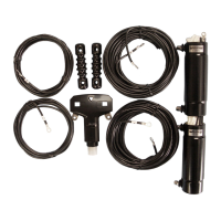
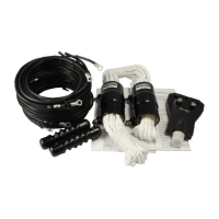
Lists all components included in the package for each W-Series antenna model.
Details the key features and materials used in the W-Series antennas, such as low stretch ratio wire and wideband balun.
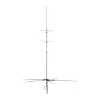
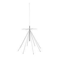
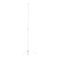
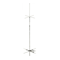
Illustrates the assembly of W-8010, W-735, and W-721 antennas, showing placement of elements and traps.
Step-by-step instructions for assembling wire elements through baluns, traps, and insulators.
Guidance on waterproofing the coaxial cable connector using self-melting plastic tape.
Advises on locating antenna ends away from walls to prevent electric shock and TVI.
Recommendations for routing coaxial cable to avoid VSWR issues.
Suggests using elastic materials to prevent antenna element breakage from strong winds.
Discusses the impact of antenna height on propagation impedance and resonant frequency.
Instructions for preparing and using a VSWR power meter for antenna adjustment.
Method of cutting adjustment elements to achieve the desired resonant frequency and minimize VSWR.
Advice on adjusting antenna height or location if VSWR cannot be improved by cutting elements.
Provides a chart showing resonant frequency change per 1cm of element cut for different bands.
Demonstrates how to calculate the required length to cut from an adjustment element for a specific frequency.
Explains how to add a 15m band to the W-735 antenna by installing a self-made element.
Presents VSWR charts for W-8010, W-735, and W-721 antennas across various frequency bands.
Summarizes key specifications for W-8010, W-735, and W-721 models, including frequency, impedance, and power rating.
| Impedance | 50 Ohms |
|---|---|
| Polarization | Vertical |
| VSWR | 1.5:1 |
| Length | 96 inches |
| Height | 96 inches |
| Radome Material | Fiberglass |