EasyManua.ls Logo

Diamond Antenna F23A User Manual

Default Icon
2 pages
To Next Page IconTo Next Page
Page #1 background imageLoading...
Page #1 background image
Description
1. Three piece joint FRP element
structure employing newly
developed direct joint system
enables the antenna to:
(A) Achieve enough strength to
compete with one piece
structure element by
overlapping upper and lower
FRP element directly.
(B) Obtain perfect waterproof
structure at the element joint
section by using ring gasket.
(C) Assemble or disassemble if
necessary by simply fastening
or loosening of few connec-
tion points.
2. Unstable vswr caused by weather
conditions is eliminated by perfect
waterproof structure. In addition,
anti-corrosion and rust free
structure of the antenna enables it
to be used at seaside or
contaminated industrial areas
without any precautions.
3. DC ground structure of the antenna
protects the radio equipment from
high voltage caused by thunder
lightening.
4. Element length and the parameter
of the phase inductor ar
e
determined by our years of
experience and experiments to
have maximum high performance.
5. C-LOAD structure employed at
the upper element improves the
propagation efficiency of the
antenna better than conventional
two-element vertical antenna.
Specifications
FREQUENCY: 144-148 MHz
GAIN: 7.8 dB
POWER: 200 Watts
IMPEDANCE: 50 Ohms
VSWR: less than 1.5:1
MAX WIND
RESISTANCE: 40m/sec (112 MPH)
MAST DIAMETER
ACCEPTED: 30-62mm
(1-1/5” to 2-2/5”)
LENGTH: 4.53m (178.3”)
WEIGHT: 1.6 kg (3.5 lbs.)
CONNECTOR: UHF Female
WARRANTY: 1 Year against
defects in material
or workmanship.
Adjustment
The F23A is completely adjustment
free. If vswr of the antenna is
extremely high. It is most likely due
to trouble in a contact point some-
where. Be sure to see if those contact
points are firmly fastened or correctly
soldered. And coaxial cable connected
to the antenna has to be those of
50ohm impedance.
Note: Though the F23A employs DC
ground structure, circuit across the
center conductor and ground section
is open circuited it is measured by
volt-ohm meter. If it is close circuited,
be sure to see coaxial cable and con-
nector section carefully.
F23A
         
        
        

2m 5/8 Wave Three-Element High performance FRP Shell Gain Vertical Antenna
DIAMOND ANTENNA Products are distributed by RF PARTS COMPANY
435 S. Pacic S treet San Marcos, CA 920 78 (770) 614-7443
www.diamondantenna.net
Question and Answer IconNeed help?

Do you have a question about the Diamond Antenna F23A and is the answer not in the manual?

Diamond Antenna F23A Specifications

General IconGeneral
BrandDiamond Antenna
ModelF23A
CategoryAntenna
LanguageEnglish

Summary

Antenna Description

Three Piece Joint FRP Element Structure

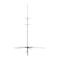
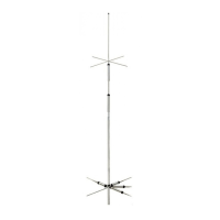
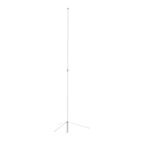
Features a three-piece joint FRP element structure for easy assembly and durability.

Weatherproof and Anti-Corrosion Design

Ensures stable VSWR and usability in seaside/industrial areas due to waterproof design.

DC Ground Structure for Protection

Protects radio equipment from high voltage caused by lightning.

Optimized Element Length and Phase Inductor

Element length and phase inductor are determined by experience for maximum performance.

C-LOAD Structure for Efficiency

C-LOAD structure at the upper element improves propagation efficiency over conventional designs.

Antenna Adjustment

Assembly Instructions

Connect Upper and Middle Elements

Securely connect the upper and middle elements using set screws.

Assemble FRP Shells

Insert upper FRP shell into lower FRP shell and fasten with joint bracket.

Connect Middle and Lower Elements

Securely connect the middle and lower elements using set screws.

Assemble Lower Shell Sections

Insert middle element shell into lower element shell and fix with joint brackets.

Fasten Connecting Sections

Firmly fasten each connecting section to ensure no gap between shells.

Attach Radial Elements

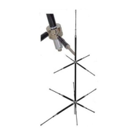
Attach the three radial elements as shown in Fig. A.

Attach Mast Brackets and Feedpoint

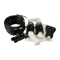
Secure mast brackets, connect coaxial cable to feedpoint, and attach support pipe.

Mount Antenna to Mast

Attach the antenna to the mast, considering its overall balance.

Safety and Installation Precautions

General Safety Warnings

Precautions for safe assembly and installation, including avoiding power lines and working alone.

Fatal Accident Avoidance

Guidelines to avoid fatal accidents, such as not touching fallen antennas near power lines.

Accident Response

Instructions on how to respond in case of accidental contact with a live electric power line.

Installation Location Factors

Considerations for antenna installation location, propagation direction, obstacles, and safety.

Related product manuals