Do you have a question about the Diamond Antenna W-735 and is the answer not in the manual?
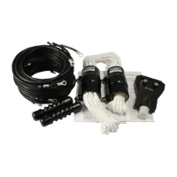
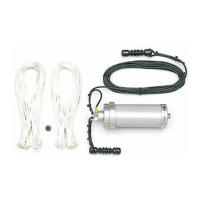
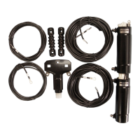
Lists all components included with the W-8010 and W-735 antennas for verification.
Explains the key features and benefits of the W-Series antennas.
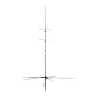
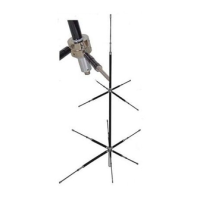
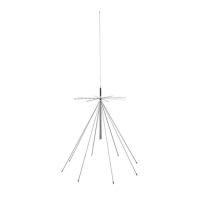
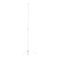
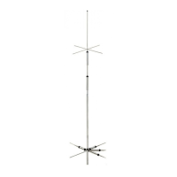
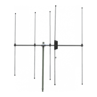
Illustrates the final assembly of the W-8010 and W-735 antennas.
Details steps for attaching wire elements to the balun and installing traps.
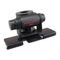
Covers attaching insulators and connecting the coaxial cable for waterproofing.
Advises on locating antenna ends away from walls to avoid shock and interference.
Guides on securing coaxial cable to prevent VSWR issues.
Recommends using elastic materials for wind resistance and discusses height effects.
Details how to prepare and use a VSWR meter for antenna adjustment.
Explains cutting adjustment elements to achieve desired resonant frequencies.
Provides advice for improving VSWR when it cannot be lowered by cutting elements.
Provides an example calculation for determining element length based on frequency difference.
Describes how to add a 15m band to the W-735 antenna.
Summarizes key technical specifications for W-8010 and W-735 models.
| Brand | Diamond Antenna |
|---|---|
| Model | W-735 |
| Category | Antenna |
| Language | English |