Finishing tasks
Slowly open the shuto valves upstream and downstream of the
HYDRUS.
Check for possible leaks at the connections.
The HYDRUS must always be completely lled with water.
Failure to use provided ber gaskets or equivelant may result in
connection leaks and damage to the HYDRUS.
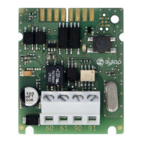
6.2 Non-return valve
If desired, the HYDRUS can be delivered with a non-return valve (accessory).
This valve must be installed in the discharge of the HYDRUS.
5
/8
" x
3
/4
'';
3
/4
" S;
3
/4
" L (see Fig. I, page 2) NSF certied
1" (see Fig. II, page 2) NSF certied
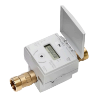
7. Communication
The HYDRUS has dierent communication interfaces:
Optical
Encoder
7.1 Optical interface
The HYDRUS can be congured by using the integrated optical interface.
IZAR@MOBILE2 software is used to read data and set parameters. This
software can be found at https://www2.diehl.com/metering/en/diehl-
metering/support-center/downloads.
If an error occurs during conguration, conguration must be started
again using the optical interface.
For correct conguration, place the opto head on the optical interface of
the HYDRUS.
We recommend the Bluetooth Opto Head IZAR OH BT for conguration.
-8-
HYDRUS
English