-10-
English
Italiano Dansk Svenska
Type B (brass) - slide the fastening screw onto the temperature sen-
sor and attach the fastening screw with the dowel pin. Press in the
dowel pin completely and remove the mounting pin from the tem-
perature sensor.
5. Insert the temperature sensor with adapter tting into the ball valve
and tighten fastening screw by hand (2-3 Nm).
3.3.2 Installation in a pocket
In case of new installations, temperature sensors for nominal sizes DN25
or smaller should only be installed immersed.
This ensures higher measuring accuracy.
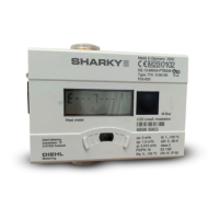
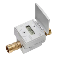
3.4 Installing the integrator
Pay attention to sufcient distance between integrator and pos-
sible electromagnetic sources of interference (switches, electric
motors, uorescent lamp, etc.) during installation.
For medium temperatures from 90 °C or for T
Water
< T
Ambient
(cooling
meter application) the integrator must be removed and tted at a suf-
cient distance from any heat/cold sources. The adapters VI A or VI B are
available.
3.5 Functional testing
After installation of the meter, putting into operation and functional test-
ing can be performed.
Proceed as follows:
Open the stop valves
Check system for tightness
Bleed the system till the ow indication is stable. Adjust the system by
means of the ow indication
After a short while the message "E-7" disappears in the display.
Press the push button next to the display and check the displays for
temperature and ow for plausibility.
Attach tampering protection at the integrator and the temperature
sensors.
Read and note meter data for energy, volume and serial number.