Setup & Installation Manual
Page 6
SD8 Quick Start Guide
If you trying to get sounds from the mixer without reading the whole installation and operating manuals, please at least read this page first!
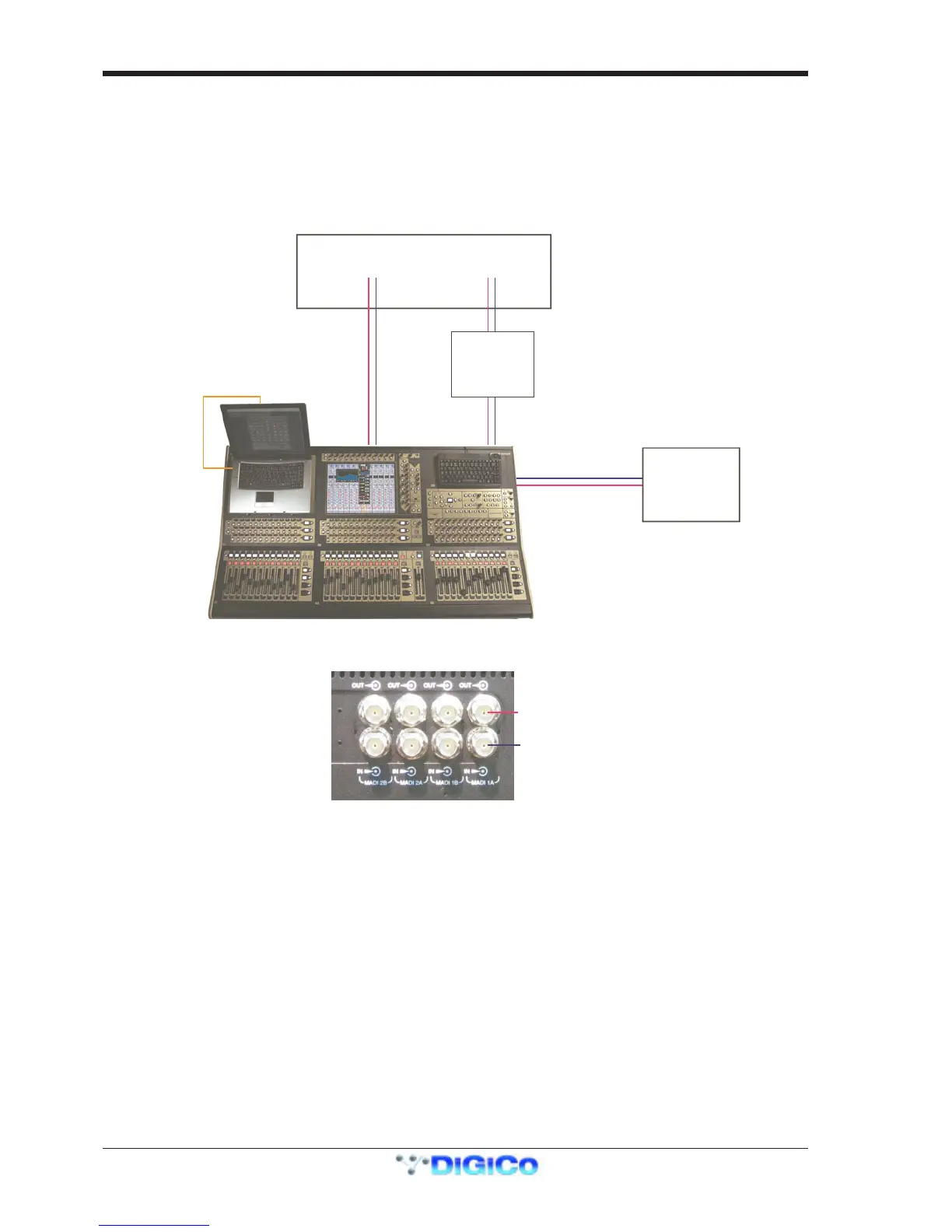
Single Console with 1 MADIRack ................................................
Detailed information on the various systems of connection is provided in the user manual but the following diagram provides an
overview of a single console/single rack setup.
Optional Remote Control
Laptop connection with
econd MaDiRack
All connections should be made before switching on the console and racks.
The console and rack each have dual redundant power supplies and both should be switched on at all times. After switching on the
console the software will be launched automatically and the state of the worksurface and settings should be the same as when it was last
Shut Down.
To Shut Down the console press the System>Shut Down button and wait until you receive a message saying that it is safe to switch the
power off.
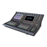
The SD8 worksurface has 8 analogue I/O and 8 AES I/O on its rear panel and additional I/O is supplied in the form of a remote MaDiRack
which has 48 analogue inputs and 8 analogue outputs as standard. This rack is connected to the worksurface by 2 x 100M high specifica-
tion 75 Ohm coaxial cables fitted with BNC connectors. This MaDiRack has two pairs of MADI connectors - Main MADI IN & OUT and
AUX MADI IN & OUT.
In normal operation the MADI connections should be as follows (see diagram below):
Rack MAIN MADI IN connected to the console MADI 1A OUT
Rack MAIN MADI OUT connected to the console MADI 1A IN
Note - Optionally, a second set of MADI cables can be connected to provide MADI redundancy from the rack’s AUX
MADI ports to the console’s MADI 1B ports
The console’s MADI Port 2 can be connected to a MADI recorder( See Audio I/O Panel for setup details) or a second DiGiCo Rack or
console.