Do you have a question about the DigiDesign 192 I and is the answer not in the manual?
Details the 16-channel digital audio interface's capabilities and connectivity options.
Lists the items provided with the 192 I/O unit, including cables and documentation.
Outlines the necessary Digidesign-qualified Pro Tools|HD system for the 192 I/O to function.
Explains the purpose of the guide, which is to provide a hardware overview of the 192 I/O.
Describes the symbols and conventions used throughout the document for clarity and ease of understanding.
Highlights the resources and services available on the Digidesign website for product information and support.
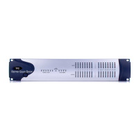
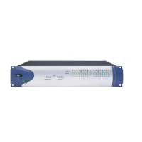
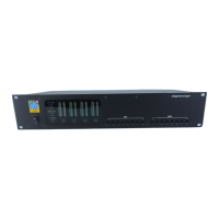
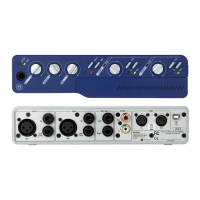
Details the physical layout and controls on the front of the 192 I/O unit.
Explains the function of the power button and the meaning of the LED ring indicator.
Describes how the sample rate LEDs indicate the internal crystal oscillator's current setting.
Explains the function of the Loop Master LED, indicating the master peripheral in a Pro Tools HD system.
Details the Sync Mode LEDs and their indications for different clock sources (Internal, Digital, Loop, External).
Explains the four-segment LEDs that indicate signal levels for input and output channels.
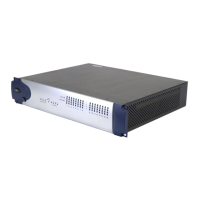
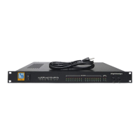
Provides an overview of the back panel connectors and bays for I/O cards.
Describes the four bays for I/O cards, including factory-installed and expansion bays.
Details the analog audio input connectors, including +4 dBu and -10 dB(V) balanced options.
Explains the dedicated input trims for calibrating analog input channels and flexibility in headroom settings.
Describes the single DB-25 connector and output trims for eight channels of analog audio output.
Details the output trims used to individually calibrate each channel's output level, with two sets available.
Covers connectors for AES/EBU, TDIF, and Optical (ADAT) I/O, and digital format compatibility.
Describes the non-removable connectors on the enclosure, including AES/EBU, Optical, and S/PDIF.
Details the enclosure's balanced XLR AES/EBU connectors and their sample rate support.
Describes the RCA jacks for S/PDIF input and output, and their audio data stream support.
Explains the enclosure's optical ports for ADAT and S/PDIF, and their sample rate capabilities.
Provides background on Lightpipe technology and its role in digital audio connections.
Details the Loop Sync ports for synchronizing multiple Pro Tools HD peripherals using a word clock signal.
Explains the use of BNC connectors for synchronizing the 192 I/O with external word clock signals.
Describes the AC power connector and the unit's auto power-selecting capability.
Explains the function of the Primary DigiLink port for connecting Pro Tools HD cards.
Lists the available lengths of DigiLink cables and their supported session sample rates.
Details how the Expansion port connects additional Pro Tools HD audio interfaces.
Describes the port for connecting older MIX-series Digidesign audio interfaces.
Outlines the restrictions on using Legacy and Expansion ports simultaneously and for higher sample rates.
States that the accessory port is not supported by the 192 I/O.
Provides instructions on how to use the input and output trims for calibration and setting headroom.
Explains the adjustable input trims for precise calibration and switching between headroom settings.
Discusses how to determine and set appropriate input operating levels based on connected equipment.
Guides users on how to switch between +4 dBu and -10 dB(V) input levels in the Hardware Setup dialog.
Explains the optional soft limiter for inputs to protect against clipping and distortion.
Details the two sets of output trims (A and B) for different headroom calibrations.
Covers how to configure digital formats and enable real-time sample rate conversion within Pro Tools.
Provides step-by-step instructions for installing an optional card into the expansion bay of the 192 I/O.
Explains how the Hardware Setup dialog reflects newly added or removed I/O cards.
Provides solutions for common issues, such as the power ring not turning green.
Guides users on how to safely remove an I/O card from the 192 I/O for servicing or replacement.
Describes how the Hardware Setup dialog is updated after removing an I/O card.
Provides a detailed pinout diagram for the 8-channel analog output DB-25 connector.
Offers a pinout diagram for the 8-channel +4 dBu analog input DB-25 connector.
Presents the pinout diagram for the 8-channel -10 dB(V) analog input DB-25 connector.
Shows the pinout diagram for the 8-channel AES/EBU digital input/output DB-25 connector.
Displays the pinout diagram for the 8-channel TDIF digital input/output DB-25 connector.
Explains the concept of calibration for digital recording devices and its difference from analog calibration.
Discusses the concept of headroom for analog and digital devices and its implications for audio signals.
Outlines the general procedure for calibrating analog devices to a mixing console's output level.
Explains how to achieve headroom on digital devices by aligning console signals to levels below full scale.
Details the process of calibrating the 192 I/O using Pro Tools' Calibration mode and Signal Generator plugin.
Provides instructions for calibrating the input level trim pots of the 192 I/O using Pro Tools.
Discusses calibrating systems with mixed Digidesign interfaces for consistent headroom levels.
| Sample Rates | 44.1, 48, 88.2, 96, 176.4, 192 kHz |
|---|---|
| Connectivity | DigiLink |
| Word Clock | Yes |
| Form Factor | Rackmount |
| Type | Audio Interface |
| Channels | 8 |
| Bit Depth | 24-bit |
| Compatibility | Pro Tools HD |
| Clock I/O | Word Clock In/Out |
| Power Supply | Internal |
| Converter Type | A/D and D/A |
| Analog Inputs | 8 |
| Analog Outputs | 8 |
| Digital Inputs | AES/EBU, S/PDIF |
| Digital Outputs | AES/EBU, S/PDIF |
| Connectors | XLR |