96i I/O Guide6
Loop Master LED
The LOOP MASTER LED indicates which
Pro Tools|HD audio interface is the master
Pro Tools peripheral. Loop Master defaults to
the first Pro Tools|HD I/O connected to the core
Pro Tools|HD card. On Pro Tools|HD (for PCIe)
this is the Accel Core card. On Pro Tools|HD (for
PCI) this is the HD Core card.
The Loop Master LED is always lit when only a
single interface is present, regardless of the syn-
chronization mode.
In expanded systems, only one Pro Tools|HD
I/O can be Loop Master at a time. When you
change the clock source to an external clock on
a Pro Tools|HD I/O, it automatically becomes
the Loop Master and all other Pro Tools|HD I/Os
in the chain switch to Loop Slave mode.
Sync Mode LEDs
The SYNC MODE LEDs indicate the current
Pro Tools Clock Source and Sync mode:
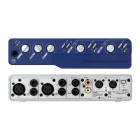
INT (Internal) Indicates the 96i I/O is the
Pro Tools clock master.
DIG (Digital) Indicates that an external digital
source is providing master clock to Pro Tools at
the 96i I/O S/PDIF port.
LOOP (Loop Sync) Indicates that the 96i I/O is
slaving to another Pro Tools|HD I/O through
Loop Sync.
EXT (External) Indicates the 96i I/O External
Clock In port is providing master clock to
Pro Tools.
For more information on Pro Tools clock op-
tions, see the HD Setup Guide.
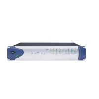
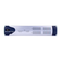
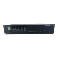
Input and Output LEDs and Meters
16 sets of four-segment LEDs indicate signal
level for each of the 96i I/O input channels.
These meter LEDs indicate –42 dB, –18 dB,
–6 dB, and 0 dB (from bottom to top), refer-
enced to Full Scale digital.
Two additional LEDs, located to the left of the
meters, indicate whether the meters display in-
put or output levels; the meters indicate input
levels by default, and can be switched from the
Hardware Setup dialog in Pro Tools.
Full Scale digital (0 dBFS) does not always
indicate signal clipping levels. Use the on-
screen meters in Pro Tools to determine
whether a signal is clipping. For more infor-
mation, see the
HD Setup Guide.