DVM-500Plus Installation Guide 002-0501-02 REV C Page 16
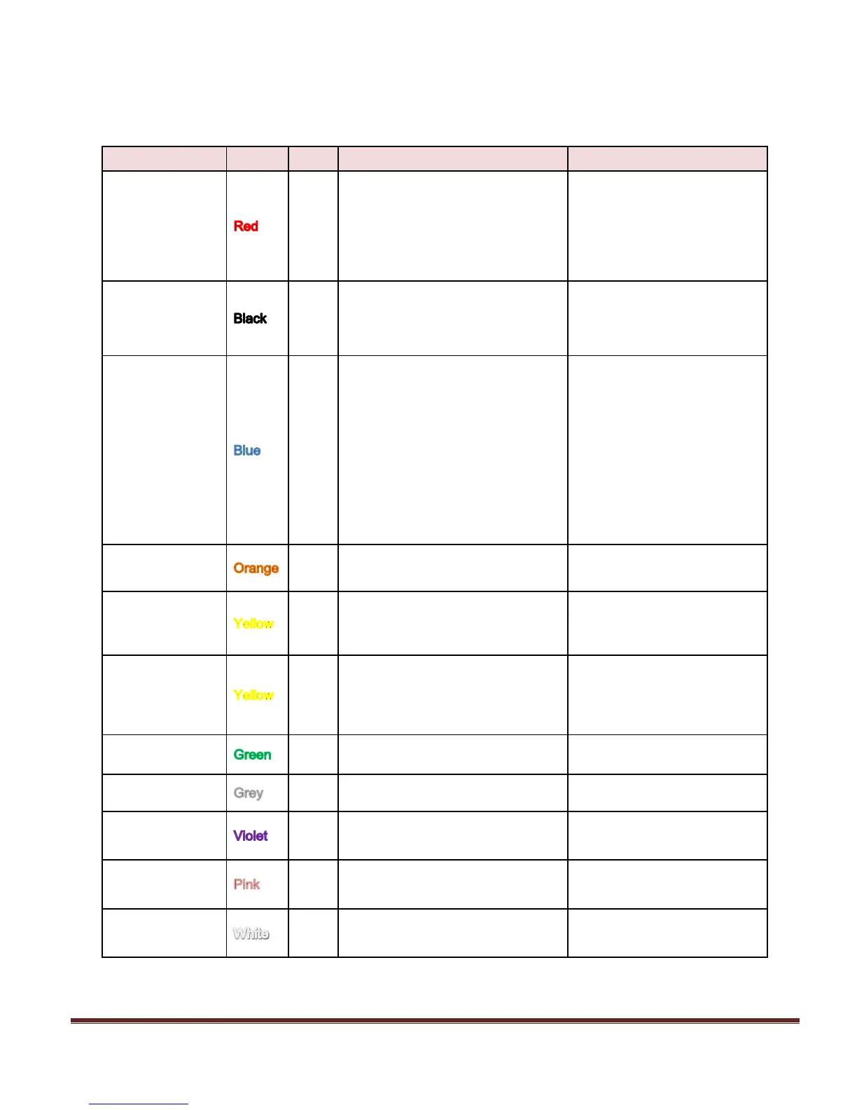
Wiring Connections Chart
REQUIRED. Digital Ally
recommends connecting
directly to the engine
compartment battery. Do NOT
connect through a charge
guard or battery saver system.
REQUIRED. Digital Ally
recommends connecting
directly to the engine
compartment battery
REQUIRED. +12V power only
when ignition is in the ACC or
On position. When ignition is
turned off, the unit Can be set
to do a controlled shutdown
automatically based on a user
selectable time setting. This
connection also necessary to
charge the I/O box internal
backup battery.
Emergency Light interface. +12V
when lights are activated
Connect to Light Bar
Controller
Connect directly to one side of
siren speaker. Or, connect one
yellow wire to siren controller if it
outputs +12VDC when siren is ON.
Connect directly to other side of
siren speaker. Or, connect other
yellow wire to ground if the siren
controller outputs +12VDC when
siren is ON.
Brake interface. +12V signal when
brakes are activated
Connect to brake pedal switch
or 3rd brake light
Vehicle speed sensor for
speedometer interface. (VSS)
Speed sensor that outputs X
number of pulses per mile.
Left turn signal input. +12V signal
when turn signal is activated
Right turn signal input. +12V signal
when turn signal is activated
Reverse input. Signal grounded
when vehicle goes into reverse