EasyManuals Logo

Digital Dream EC500 User Manual

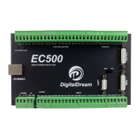
Digital Dream EC500
25 pages
To Next Page IconTo Next Page
To Previous Page IconTo Previous Page
Page #11 background imageLoading...
Page #11 background image
As the Picture 5-1 showed. the marked No. 4 is General output interface. This is a DB15 port.
5.4 General output interface
PIN No. DefinitionMark
1
2
3
4
5
6
7
8
9
10
11
12
13
14
15
COM+ IO power +
OUTPUT 6
IOUTPUT 8
OUTPUT 10
Common Ground for output
OUTPUT13
OUTPUT15
IO power +
OUTPUT 7
OUTPUT 9
OUTPUT 11
OUTPUT 12
OUTPUT 14
OUTPUT 16
VCCIO
OUT6
OUT8
OUT10
OUT7
OUT9
OUT11
OUT12
OUT14
OUT16
COM-
GND
OUT13
OUT15
Picture 5-7 EC500 Spindle Motor Max Speed Setting
Picture 5-8 General Output DB15 Pin No.
Page -9Digital Dream Mach3 Motion Controller EC500 User’s Manual

Questions and Answers:

Question and Answer IconNeed help?

Do you have a question about the Digital Dream EC500 and is the answer not in the manual?

Digital Dream EC500 Specifications

General IconGeneral
BrandDigital Dream
ModelEC500
CategoryController
LanguageEnglish

Related product manuals