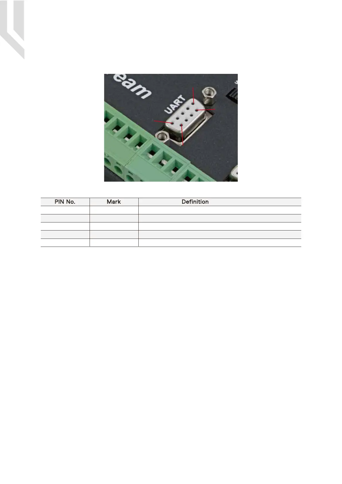
Picture 5-11 Extended Serial Port
As the Picture 5-1 show, The marked No. 7 port is Serial extend port. The interface is mainly used for
extended serial devices, such as IO extensions or HMI interface extensions.
5.6 Serial extend port
PIN No. DefinitionMark
1&6
2
3
5&9
4&7&8
VCC5 5V Power+
Receive for serial port
Transmit for serial port
Ground
Reserved
RXD
TXD
GND
NC
As the Picture 5-1 showed, Marked No. 8 position is for Input ports.They are the optical isolated
Input interface. The Mark information from left to right
is:IN1,COM-,IN2,COM-,IN3,IN4,IN5,IN6,IN7,IN8,COM-,COM+,IN9,IN10,IN11,IN12,IN13,IN14,COM
-,COM+,IN15,COM-,IN16,IN17,COM-,IN18.
Internal structure see as Picture 5-12.
2 lines Proximity Switch/ordinary fretting switch / drawing see as Picture 5-13.
3 lines Proximity Switch connection Picture 5-14 and Picture 5-15, brown cable for Proximity
switch connect with 12V,Black cable connect channel, blue cable connect with GND1. Pls note Only
support NPN typel 3 lines proximity switch.
5.7 Input Ports
1
5
6
9
Page -12Digital Dream Mach3 Motion Controller EC500 User’s Manual

 Loading...


