This document is an operating manual for Dikkan Globe Valves, providing detailed information on their function, technical specifications, usage, and maintenance.
Function Description
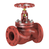
Dikkan Globe Valves are designed as linear motion valves primarily for stopping, opening, or regulating fluid flow in a pipeline. They are named for their spherical body shape. The valve disc is designed to stop flow and create a tight seal under pressure. For regulating applications, a regulating disc is used, which has a spherical shape to provide better control. Bypass discs are available for higher differential pressures.
These valves are operated manually by handwheel, with options for electric, pneumatic, or hydraulic actuators. The handwheels are designed for reasonable effort and are marked with "open" and "closed" directions, along with a directional arrow. For valves with balancing plugs, the medium flows over the plug. When the valve is closed, rotating the handwheel counterclockwise lifts a pilot plug off the larger balancing plug, allowing the medium to pass through and equalize pressure before the main valve can be opened with normal manual force.
Important Technical Specifications
Standards:
- DIN 86251, DIN86252, DIN 86260, DIN 86261, EN 13709, DIN 3356
Face to Face Dimensions:
- Straight Form - EN 558 Series 1 (DIN 3202 F1)
- Angle Form - EN 558 Series 8 (DIN 3202 F32)
Flange Dimensions:
- EN 1092-1, EN 1092-2, EN 1092-3
Materials:
- Cast Iron, Ductile Iron, Cast Steel, Stainless Steel, Bronze
Types:
- Stop Type, SDNR Type, Regulating Disc, Bypass Disc
Applications:
- Steam, fresh water, air, oil, seawater, feed water, cold and hot water, gases
Pressure & Temperature Ranges:
- Cast Iron, Ductile Iron, Bronze:
- DN15-DN200: 16 bar @ 120 °C, 10 bar @ 180 °C
- DN250: 10 bar @ 120 °C, 6 bar @ 180 °C
- DN300-DN350: 6 bar @ 120 °C, 4 bar @ 180 °C
- DN400-DN600: 4 bar @ 120 °C, 2 bar @ 180 °C
- Cast Steel, Stainless Steel:
- DN15-DN150: 40 bar @ 120 °C
- DN175-200: 16 bar @ 120 °C
- DN250-DN300: 10 bar @ 120 °C
- DN350: 6 bar @ 120 °C
- DN400-DN600: 4 bar @ 120 °C
Key Features (Globe Valves):
- Bolted bonnet
- Outside screw and yoke
- Rotating rising stem & handwheel
- Metallic or soft seating surfaces
- Special trims available
- Flanged
- Backseat
Usage Features
Installation:
- Pipelines must be installed to prevent thermal expansion tensions from impacting valves.
- The pipeline must be cleaned of dirt (sand, dust, welding residues) before installation. Strainers are recommended.
- Verify valve suitability for operating specifications (max pressure, temperature, corrosiveness, abrasiveness).
- Ensure flange distance matches valve body length.
- Remove all transport/storage protection devices before installation.
- Install with the arrow on the valve body in the direction of liquid flow. Valves without an arrow can be installed bidirectionally.
- Assemble valves to the pipeline in a fully closed position.
- Use gaskets suitable for operating conditions between valve and counter flanges.
- Flanges must be in the same axis and parallel.
- Bolting should be done in a crossover method to load the pipe and valve evenly.
- Connections should be checked for leaks with water after installation.
- SDNR type valves without springs can only be installed in horizontal pipes in a vertical position.
- Stop type globe valves can be installed in any position, but the best installation position is with the stem pointing vertically upwards.
Operation:
- To open, turn the handwheel counterclockwise. To close, turn clockwise.
- Open and close valves slowly, especially in liquid systems, to prevent pressure surges (water hammer).
- Level indicator models allow monitoring of open-close rates.
- If the handwheel is difficult to turn, loosen the packing nut 1/2 to 1 1/2 turns, then retighten after operation.
Maintenance Features
General Maintenance:
- Dikkan globe valves require minimum maintenance, but regular checks increase longevity and reliability.
- Valves must be dismounted from the pipeline and cleaned of medium before maintenance.
- Maintenance work must be performed by qualified, trained, and skilled personnel according to instructions. Welding is not accepted for valve repairs.
- For seldom-used valves, perform open-close operations every 3-4 months.
- Periodically lubricate exposed stem threads with quality grease.
- Check bonnet bolt tension periodically in high-temperature applications to prevent loosening. Replace ring gaskets if erosion or corrosion causes leaks.
Gland Packing Replacement (8.1):
- Packing replacement under pressure is dangerous and not recommended, even if the valve is back-seated.
- The backseat function should only be used to minimize leakage after shutting down the line and depressurizing. It is preferable to repack during a shutdown.
- Valves should not be kept fully back-seated during usage, as this can dry out the packing and cause leakage. After fully opening, rotate the handwheel a quarter turn towards the closed position.
- To replace, unscrew nuts (P.No15) and raise the gland (P.No12). Remove old packing with a hook, then clean the stuffing box and stem. Cut new packing into individual rings, ensuring they are fully seated and not stretched excessively.
Gasket Replacement (8.2):
- Depressurize the system and remove the valve from the pipeline before bonnet disassembly.
- Disassembling the valve without warranty consultation may void the warranty.
- Bonnet Disassembly:
- Operate the valve to full open position.
- Remove bonnet bolts (P.No17) using a crossover method.
- Lift up the bonnet assembly, taking care not to damage the disc.
- Gasket Replacement:
- Discard the old gasket (P.No4).
- Inspect the gasket seating surface for wear, damage, or deterioration.
- Polish the gasket seating surface with sandpaper to clean rust, dirt, and remnants.
- Clean the surface to remove all polishing residue.
- Install a new gasket.
- Body-Bonnet Assembly:
- Inspect bonnet bolts for damage and replace if necessary.
- Place the bonnet assembly onto the valve body, avoiding disc damage.
- Tighten bolts in a crossover method (as shown in Fig. 1).
- Test the valve and return to service.
Metal to Metal Sealing Repair (8.3):
- For small defects in the seat sealing surface, lapping with a special tool is possible.
- Remove the valve from the pipeline.
- Procedure:
- Apply thick polishing paste. Alternately turn clockwise and counterclockwise about 90°, pressing softly. Lift and turn the tool frequently to change contact position. Continue until defects disappear, adding more paste as needed. Clean the seat and repeat with a thinner polishing paste.
- Remove the lapping tool and clean the seat with a washing agent.
- Check for proper contact using marking blue: Coat body seats with marking blue, press the disc into the seats by hand, and examine for continuous contact.
- If contact is not homogeneous, repeat steps. If the disk defect is greater, metal cutting on a lathe can be performed, followed by lapping.
Storage and Transport:
- Store valves in a closed place away from direct sunlight.
- Keep valves on pallets, avoiding direct ground contact.
- Protect from external effects, mechanical damage, dust, and dirt.
- Keep packaging until installation. Avoid sudden temperature changes in the storage area to prevent sweating.
- Keep away from heat and flame sources.
- Protect from excessive vibration during transportation.
- Optimum storage temperature: 5°C to 40°C.
- Ensure valve discs are in the closed position during storage (except for soft seal valves).
- Unload valves carefully from wooden pallets without dropping. Lift by the body, not the trim.
- Periodically verify the condition of stored products.
Safety Remarks (12):
- Observe operating instructions; non-compliance voids warranties.
- Sharp edges and burrs can cause injuries.
- Valves must be mounted, started up, or serviced by fully trained and qualified personnel.
- Maintenance staff must be informed of dangers related to disassembling/mounting valves and electrical/machinery installations.
- Use safety goggles and other appropriate protective gear.
- Ensure the plant is depressurized and no medium can leak from the pipeline before working on a valve.
- Ensure dangerous/combustible/detonating gas or fluid is depressurized from the product and connected piping.
- Preserve valve-specific maintenance manuals and make them accessible to maintenance staff. Staff must read manuals before any use or maintenance.
Warranty (14):
- Warranty Period: 18 Months.
- The warranty covers maintenance work, installation of external parts. Unoriginal parts used for replacement, warranties, and liabilities become invalid.
Pressure Equipment Directive (2014/68/EU) and CE Marking (11):
- Dikkan globe valves comply with the European Pressure Equipment Directive 2014/68/EU.
- Valves are categorized based on maximum working pressure, size, and hazard level (fluid group 1: dangerous, group 2: all other fluids including steam).
- Categories include SEP (sound engineering practice), I, II, III, or IV.
- SEP valves do not bear the CE mark or require a Declaration of Conformity.
- Dikkan valves with CE marking have a declaration of conformity, including information on the applied conformity assessment procedure, confirming quality assurance in design, manufacture, and final acceptance by a notified body.