Advanced Force Gauge User’s Manual
20
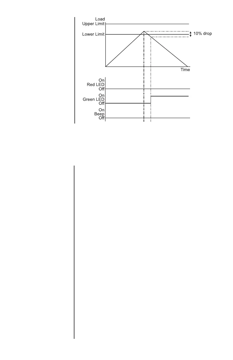
Example 5
Settings: -
- BOTH LED and audio
alarms are active
- Alarm triggers on OUT
BAND
- Alarm is set to FAIL
- % DROP is 10% of
fullscale (e.g. AFG
100N must register
drop of 10N)
Main display is set to
1st peak tension
screen
PLC
(Programmable Limit
Controller)
PLC sub-menu 1
The AFG has a load output signal which may be used
for PLC applications. For PLC applications, this
function requires an external cable with a built-in
solid-state relay – see Specifications for details of the
signal.
To configure the signal output from the AFG, press
and hold the MENU key until page 1 of the main menu
appears. Press DOWN to move the arrow cursor to
PLC and press the ENTER key. The cursor arrow now
points to PLC OFF.
The display will show:
PLC OFF Indicates PLC function status.
RESET When the load limit is reached, the
output signal triggers the relay and
the RESET key must be pressed to
clear the line before starting the next
test.
CONTINUOUS The relay will be activated every time
the load limit is reached and the
output signal will remain on.
PULSE The relay will be activated momen-
tarily when the load limit is reached.
Select the desired function and press the ENTER key.