Do you have a question about the DIMLUX MAXI CONTROLLER EVO 1.2 and is the answer not in the manual?
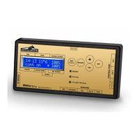
Regulates and operates lighting, CO2, VPD status, and connected components.
Measures room temperature, requires shading for accuracy.
Measures relative humidity for VPD and climate control. Needs shading.
Accurately measures and controls room CO2 levels for generators or ventilation.
Measures crop temperature to assess vaporization, crucial for VPD calculation.
Extends controller functionality for heating, humidification, dehumidification, and fan control.
Connects controller to Dimlux ballasts/fixtures via signal cable and interlink cables.
Connects CO2 sensor to controller and CO2 generator/pressure-reducing valve.
Connects auxbox to controller's AUX port via a communication cable.
Connects sensors (temp, RH%, PT camera) to controller for VPD calculation.
Explains basic and advanced menus, and essential keys for navigation and control.
Settings for current time, timer ON/OFF, and ballast/light fixture type in basic mode.
Details advanced keys for comprehensive control, including OFF/MODE and ESCAPE functions.
Configures time, date, timer, countdown, rise/fall, and temperature limits for lighting.
Setting the current time and date for accurate controller operation and scheduling.
Setting ON/OFF timers and countdowns for precise light cycle management.
Simulating sunrise/sunset and defining temperature limits for lighting control.
Choosing the correct light fixture/ballast type for output control.
Setting how lights behave after a power interruption (CONTINUE/HOLD).
Controlling the LCD screen backlight to be always ON or AUTO OFF.
Selecting between Celsius and Fahrenheit for temperature display.
Choosing to display output status in Watts or percentages.
Enabling independent control of two separate rooms via OUT1 and OUT2.
Accessing CO2 SmartLogic, calibration, and manual settings for precise CO2 management.
Calibrates the CO2 sensor to 400 ppm by exposing it to outdoor air.
Setting up fan control parameters based on temperature and humidity for optimal climate management.
Manually adjusting CO2 sensor readings to correct any displayed deviations.
Setting start and stop times for CO2 dosing relative to light cycles for efficiency.
Defining a night temperature setpoint for heating using the CO2 generator.
Configuring fan speed, temperature, and humidity modes for advanced climate control.
Setting humidification or dehumidification based on RH% setpoints for day and night.
Preheating the room before lights activate to prevent condensation issues.
Controlling an external heater to maintain room temperature when lights are off.
Adjusting plant temperature camera readings for accuracy against room temperature.
Calibrating the relative humidity sensor for precise measurements.
Displays maximum and minimum values for all sensors with timestamps.
Shows highest and lowest room temperature readings and the times they occurred.
Shows highest and lowest relative humidity readings and the times they occurred.
Shows highest and lowest plant temperature readings and the times they occurred.
Shows highest and lowest CO2 levels with timestamps and option to reset.
Records controller events, errors, and potential issues like incorrect voltage supply.
Explains symbols displayed on the controller's main and CO2 screens.
Stores measured values on a USB stick for PC analysis and graphical viewing.
Explains LED status indicators on Dimlux ballasts for self-diagnosis.
Connects ballasts/fixtures using RJ45 plugs via Interlink cables for simpler system setup.
Defines behavior of odd numbered lights during half-force or high temperature safeguard.
Details the limit of 80 light fittings per OUT port when using original cables.
Illustrates alternative connection methods for existing or older system setups.
| Brand | DIMLUX |
|---|---|
| Model | MAXI CONTROLLER EVO 1.2 |
| Category | Controller |
| Language | English |