18 19
ENEN
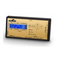
DATALOG (only EVO 2.0 Datalog)
The EVO DATALOG can be used together with a USB data stick to store all values measured by the controller
in order to view these later in graphic form on a PC. The controller writes the values onto the stick every minute.
Press the OFF/MODE key for four seconds to start the log. The message “initializing USB stick” appears
on the screen.
The 400 Watt lamp ashes once a minute to indicate that data are being written to the disk. Press the OFF/MODE
key once more for four seconds to stop the log. The message “stop logger” appears on the screen.
If the message “Fatal USB error” appears on the screen, the stick provided is probably not being sued or the stick
must be formatted.
LED indication on dimlux ballast equipment
The ballast equipment of Dimlux has an own self-diagnosis system. A red and green LED
on the ballast or light xture makes it possible to see a possible error alert and the status.
On = led on
Off = led off
Strobo = ashing very fast
Flash = ashing normally
Off-DB On-DB Off-Rem On-Rem Open Short HTP LVP HVP EOL State
Off Off Flash On On Off On Flash Flash Strobo Green
Flash On Off Off Flash Strobo On Flash On Strobo RED
Denitions of abbreviations
Off-DB = lamp off with dim button Short = Short circuit or defective lamp
On-DB = Lamp on with dim button HTP = High temperature safeguard active
Off-Rem = Lamp off with maxi controller HVP = Too high voltage (power supply)
Off-Rem = Lamp on with maxi controller HVP = Too low voltage (power supply)
Open = Open contact between the ballast and lamp or defective lamp EOL = Life expectancy of lamp
DATALOG AND DIMLUX CONNECTION OPTIONS
Interlink cable
The new EVO Maxi Controller 1.2 has a new simpler system to connect the controller to the ballasts / light xtures.
It is no longer necessary to connect a double-core cable alternately to the ballasts / light xtures. All ballasts / light
xtures can now be connected in succession through an Interlink cable using RJ45 plugs. The system's electronics now
personally ensures that the lamps switch off alternately with half-force or high temperature safeguard. (checker board
pattern) The lamps that will go OFF with half-force or with a high temperature safeguard, will now also automatically
change every 6 hours with the lamps that are switched ON, in order ensure that the light patter remains as equal and
uniform as possible under these circumstances.
The maxi controller is supplied with one 5 meter Interlink cable.
All ballasts and light xtures
600W Extreme series (remote) = 0.6 meter / 315W and 600W Expert series = 2.0 meter /
630W and 1000W Expert series = 2.5 meter
The Interlink cables are available in various lengths ( 0.6m / 1.5m / 2m / 2.5m / 3.5m / 5m / 10m ).
Ask your dealer for more information.
ROOM SETUP
Odd numbers go off at half-force or high temperature safeguard.
1
6
7
2
5
8
3
4
9