Fireplace Installation
strip the individual conductor from
the end.
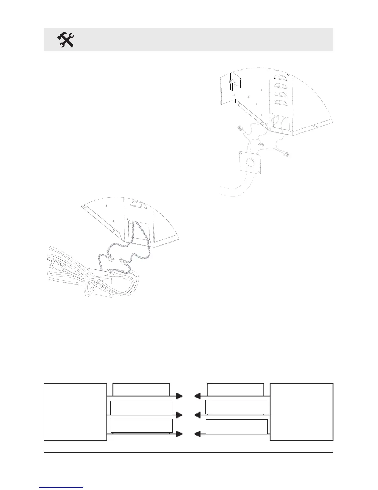
③ Loosen the screw securing
the junction box cover and
remove the cover.
④ Take the cables out from the
junction box, loosen the two wire
twist nuts and remove the cord
set (Figure 2).
⑥ Connect the black wire (live)
from the unit to the black wire
from power supply (Figure 3).
⑦ Connect the white wire
(neutral) from the unit to the white
wire from power supply
(Figure 3).
⑧ Connect the green wire
(ground) from the unit to the
green wire from power supply
(Figure 3).
Figure 2
⑤ Route the power supply wire
through the knockout on supplied
alternative junction box cover
and secure with a wire clamp (not
supplied) (Figure 3).
Fireplace
Junction
Box
White wire (N)
Black wire (L)
Green wire (G)
Green wire (G)
Black wire (L)
White wire (N)
120 V Power
Supply
(Breaker Panel)
Figure 3