13
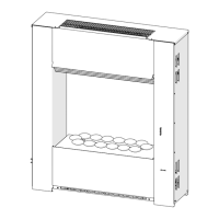
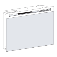
Figure 10
Flicker Rod
End Bracket
Flicker Rod Middle Bracket
LED Light Strip Bracket
side of the rebox.
Remove both sets of the three (3) end panel screws 10.
and the ve (5) front screws that hold the Media Tray in
place. (Figure 8)
Inside the lower cavity, locate the Flicker Motor and 11.
the Flicker Rod. The Flicker Rod can be removed by re-
moving the brackets, the two that are attached together
in the middle and the one at the end opposite the icker
motor. (Figure 9 & 10)
Once the screws that attach the brackets to the rebox 12.
have been removed, carefully pull and twist the rubber
gasket and reector rod off of the motor shaft, taking
care not to bend the rod. If the rod gets bent, it may
cause a rubbing noise once the replace is re-assem-
bled.
At this point the whole assembly with the brackets can 13.
be removed from the unit. The end bracket can be re-
moved from the end of the Flicker Rod and the screws
holding the center bracket can be removed as well.
Replace the old Flicker Rod with the new one and reas-14.
semble in the reverse order.
!
NOTE: Ensure that the icker rod is not bent and the
bushing in the center of the icker rod is completely set in
the support bracket. The bushing must be properly aligned
for it to go all the way down into the bracket.
Re-assemble the remainder of the replace in reverse 15.
order from the instructions above.
CAUTION: Ensure that the remote control wire antenna
is placed so that it is not caught between any of the
screws or sheets of metal.
!
NOTE: Be sure that the anges on the end panel are
positioned on the interior of the outside panel of the re-
place.
FLICKER MOTOR REPLACEMENT
Tools Required: Philips head screwdriver
Flat head screwdriver
Needle-nose pliers
WARNING: If the replace was operating prior to ser-
vicing, allow at least 10 minutes for light bulbs and heating
elements to cool off to avoid accidental burning of skin.
WARNING: Disconnect power before attempting any
maintenance to reduce the risk of electric shock or damage
to persons.
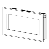
Remove the frame ller strip and carefully remove the 1.
glass or trim assembly from the unit.
Carefully remove the media from the front tray.2.
Wall Mount: 3. Remove the replace assembly from the
wall by carefully lifting it upward, releasing it from the
anges of the wall-mounting bracket. (Figure 4).
Pedestal Mount:4. Carefully lay the unit face down on a
at surface and remove the six (6) screws holding the
pedestal to the unit. (Figure 5)
Carefully set the unit upright on a at working surface.5.
!
NOTE: If necessary, lay a protective barrier between
the unit and your work surface, (i.e. cloth, cardboard, thick
plastic) to avoid scratching your work surface.
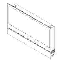
On the right end, with the controls, remove the seven 6.
(7) screws around the outside of the end panel. (Figure
5)
Remove the three (3) front panel screws along the 7.
center of the back of the unit. (Figure 7)
Lay unit on its back and remove the remaining nine (9) 8.
screws from the end panel.
Remove the end panel being careful not to add any 9.
strain to the wires connecting to the controls.
Gently guide the partially reective glass out the open 10.
side of the rebox.
Remove both sets of the three (3) end panel screws 11.
and the ve (5) front screws that hold the Media Tray in
place. (Figure 8)
Inside the lower cavity, locate the Flicker Motor. Re-12.
move the two (2) screws which secure the icker motor
to the mounting bracket and remove the motor. (Figure
9)
Carefully pull and twist the rubber gasket and reector 13.
rod off of the motor shaft, taking care not to bend the
rod. If the rod gets bent, it may cause a rubbing noise
once the replace is re-assembled.
Locate the terminal block located on the back wall by 14.
the controls. (Figure 9) Remove the three (3) icker
motor wires from the terminal block by using a Philips
screw driver to loosen the screw in each of the associ-
ated terminals. Note the original wire locations and
orientation of the capacitor.
Remove the original icker motor and remove the 15.
rubber barrier that mounts between the motor and the
bracket.
Fit the rubber barrier onto the new icker motor and 16.
mount the icker motor onto the mounting bracket. Re-
connect the rubber gasket and icker rod to the icker
motor.
!
NOTE: Ensure that the icker rod is not bent and the