Connection with the system
The following section contains general information
about the communication connections. Full wiring
diagrams and hydraulics for standard systems are
available in Section 16.
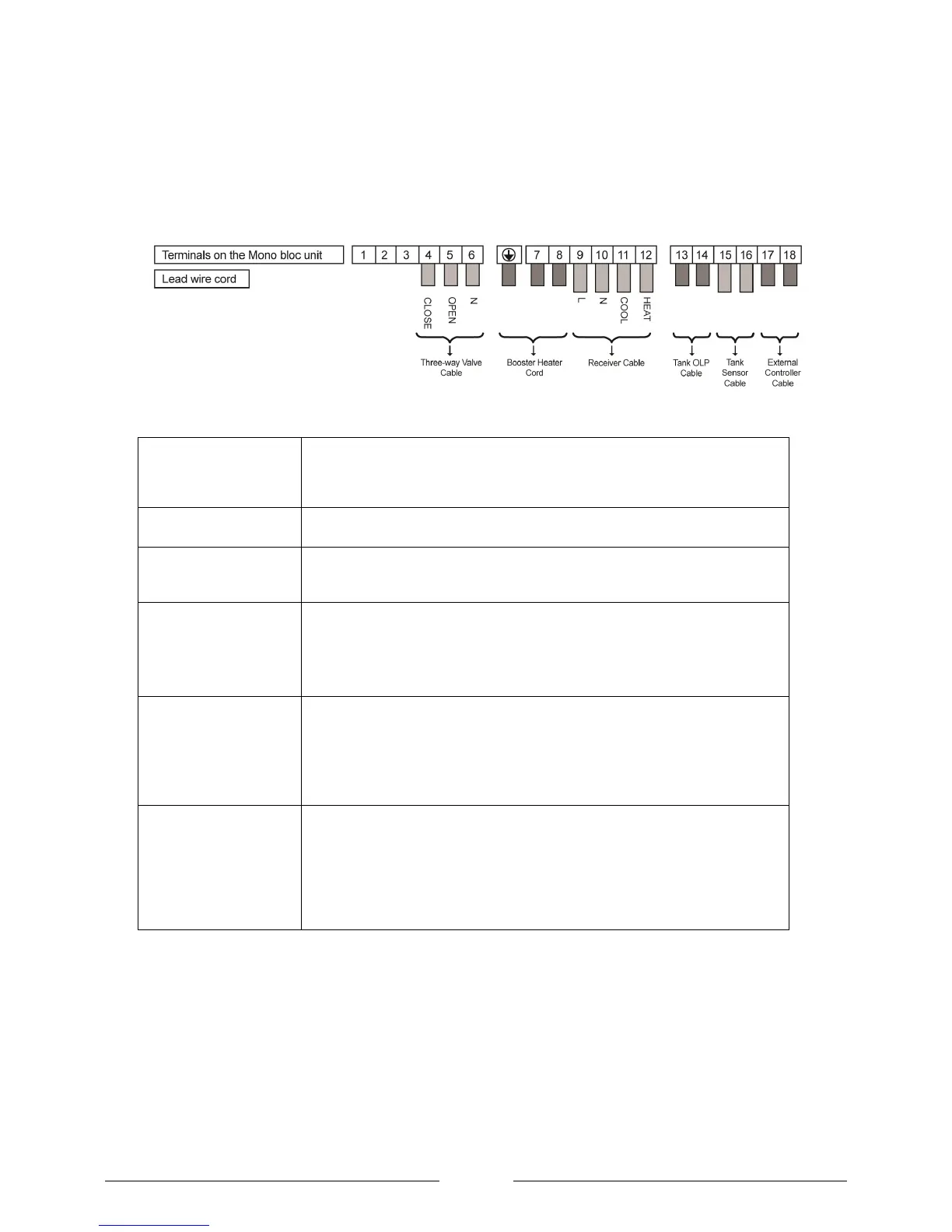
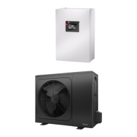
Figure 27: Heat pump communication connections
External controller cable
This can be used to remotely put the heat pump in standby mode upon breaking
the connection from an external control device. When in standby the heat pump
frost protection will still be activated. To enable this function a factory fitted jump
lead between terminals 17 and 18 must be removed.
2 x two-way valves are necessary if the heat pump needs to switch mode from
space heating to domestic hot water production.
Booster (Immersion)
heater
This is the immersion heater installed in the DHW cylinder. It immersion can
either be switched directly by the heat pump or a relay can be fitted locally to the
cylinder as shown in Figure 23.
The receiver cable is used to communicate a heating demand to the heat pump
from a device such as a wall mounted thermostat.
Connection of the receiver cable is essential to provide „boiler interlock‟ to
comply with building regulations.
If the heat pump is doing DHW, the over load protection is connected to the
manually resettable high limit stat on the DHW cylinder. Using this connection is
a way of comply with G3 building regulations.
If such connection is deemed unnecessary a jumper must be connected across
these terminals if the heat pump is programmed for DHW production.
The tank sensor is essential for DHW production because it monitors the
temperature in the DHW cylinder. The DHW sensor must be an NTC-2. This
sensor is supplied as part of the standard package.
To comply with wiring regulations it might be necessary for the sensor cable to
be different cable from the other communication cables since it is extra low
voltage and the other cables carrying 240V.
Installation of the controller
The controller should be installed:
In a place which is away from direct sunlight
and high humidity.
On a flat surface to prevent warping of the
remote controller and damage to the LCD
screen.
Where the LCD can be easily seen for
operation. (Standard height from the floor is
1.2 to 1.5 meters.)
In a location where the cable can be fed
though the wall or to the surface of the wall
and attached in such a way as not to cause
snagging.