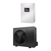
Section 7: Heating System Connection
External pipe work
The pipe work running from the heat pump into the
property should be sufficiently insulated to minimise
the heat loss and consideration should be given to
using the correct material.
Minimum water volume
The minimum water volume of the system is 50 litres
which must always be available when in heating mode
even if all of the zone valves are closed and additional
circulation pumps are off. This is typically achieved by
installation of a buffer cylinder. If a buffer cylinder is
not present there may be problems during a defrost,
namely the heating distribution system going cold and
electric immersion being required to bring it up to
temperature.
The internal volume of the heat pump is 5L.
Buffer tank
The integration of an air-to-water heat pump requires a
buffer tank connected in series to ensure that the
evaporator (finned heat exchanger) is defrosted by
means of reverse circulation. Installation of a buffer
tank connected in series also lengthens the runtimes
of the heat pump during periods of reduced heating
demand.
Minimum heating water flow rate
performance data table‟ must be observed. The
following factors should be considered:
Hydraulic resistance of the pipe work. Special
attention should to given to ensure the correct
pipe diameter is chosen considering the
required flow rates.
As a rule of thumb 28mm pipe work should be
used although the sizing of the pipe work
remains the responsibility of the installer.
To minimise energy consumption the pump
should run of the lowest speed possible whilst
still achieving the correct flow rate. The
resistance of all the pipe fittings, filter, heat
emitters and condenser must be taken into
account.
Failure to observe the minimum water throughput will
cause the heat pump not to work due to operation of
the flow switch alarm (H62).
The maximum water throughput is 20% more than the
stated minimum water throughput. Exceeding the
maximum flow rate would result in an inefficient
system operation due to increased pumping losses.
For systems in which the heating water flow can be
shut off via actuators or thermostatic valves an
overflow bypass valve must be installed to guaranteed
to minimum water flow rate.
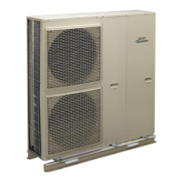
Taconova flow checker
The Taconova flow checker is provided in every
system package to provide a simple way to verifying
that the flow rate is correct. The flow rate is read on
the bottom of the spinner as shown in
Figure 11: Correct reading of flow rate on the taconova
flow checker
The flow checker should be installed in a visible
location inside the property and as close to the heat
pump flow as possible. In order given an accurate
reading the pipe installation distances shown in Figure
12 should be observed as well as the flow direction as
shown in Figure 13.
When connecting the heating system, all
applicable regulations must also be adhered
to including all relevant European and
national regulations (including EN61770), and
local building regulation codes.
Work that requires the covers to be removed
must only be carried out under supervision of
qualified contractor, installation engineer or
service person.
The installation of an air source heat pump
must be carried out by a Dimplex Qualified
installer.