Do you have a question about the Dimplex A16M and is the answer not in the manual?
Details regarding the manual's scope, intended audience, and usage guidelines.
Critical safety precautions, warnings, and guidelines for installation and operation.
Defines the product's purpose and limitations for domestic and light commercial applications.
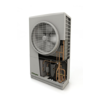
Illustrates and identifies external labels and connection points on the heat pump unit.
Provides key physical dimensions and mounting hole details for the heat pump unit.
Lists components included in different installation packs for space heating and DHW.
Outlines the process for notifying the Distribution Network Operator before grid connection.
Guidance on selecting the correct heat pump size based on system requirements and standards.
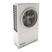
Recommendations for optimal placement of the outdoor unit, considering airflow and clearances.
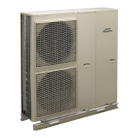
Instructions for correctly mounting the heat pump onto a suitable plinth and securing it.
Key considerations and requirements for plumbing installations, including pipe sizing and connections.
Details on electrical connections, wiring regulations, and safety measures for the heat pump system.
Information on the user interface, its functions, and the initial startup sequence.
Step-by-step guide for commissioning the heat pump system, including various checks and settings.
Routine checks for the heat pump unit's physical condition and cleanliness.
Verifying the security and correctness of electrical connections and supply voltage.
Checking system pressure, water leaks, and the condition of the return pipe strainer.
Assessing room temperatures, heating times, and if heating curves require adjustment.
Detailed performance data, dimensions, electrical characteristics, and design features.
Schematic illustrating the refrigerant flow and components within the heat pump system.
Plumbing schematic illustrating a zone system with a circulating pump and open by-pass.
Plumbing schematic for zones without circulating pumps and with a spring-loaded by-pass.
Schematics covering single to four zone space heating configurations.
Schematics for zoned systems including domestic hot water functionality.
Schematics for bivalent space heating systems with various zone configurations.
Schematics for bivalent zoned systems with DHW functionality.
Diagrams for wiring centre connections without an A-Class cylinder.
Diagrams detailing wiring centre connections when using an A-Class cylinder.
Illustrates jumper settings on SEC board, water module, and user interface for recommended setup.
Detailed diagrams for connecting the user interface and heat pump via controller cables.
Visual guide of the installer menu structure and the sequence of operations.
Template for recording installation details, system parameters, and test results.
Document certifying compliance with relevant EU directives and applied standards.