Millbrook House, Grange Drive, Hedge End, Southampton, SO30 2DF
25
4.2 Electrical Information
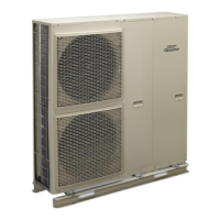
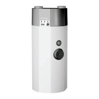
The heat pump system consists of the heat pump, wiring centre and user interface. If a Dimplex A-Class
cylinder is also used, the wiring centre is built into the cylinder.
The user interface acts as a thermostat and is sufcient if one heating zone is present. Optional, additional
temperature probes or room thermostats are required for additional heating zones.
The wiring diagrams in the Appendices section show the different possible wiring congurations for
systems with and without a Dimplex A-Class cylinder.
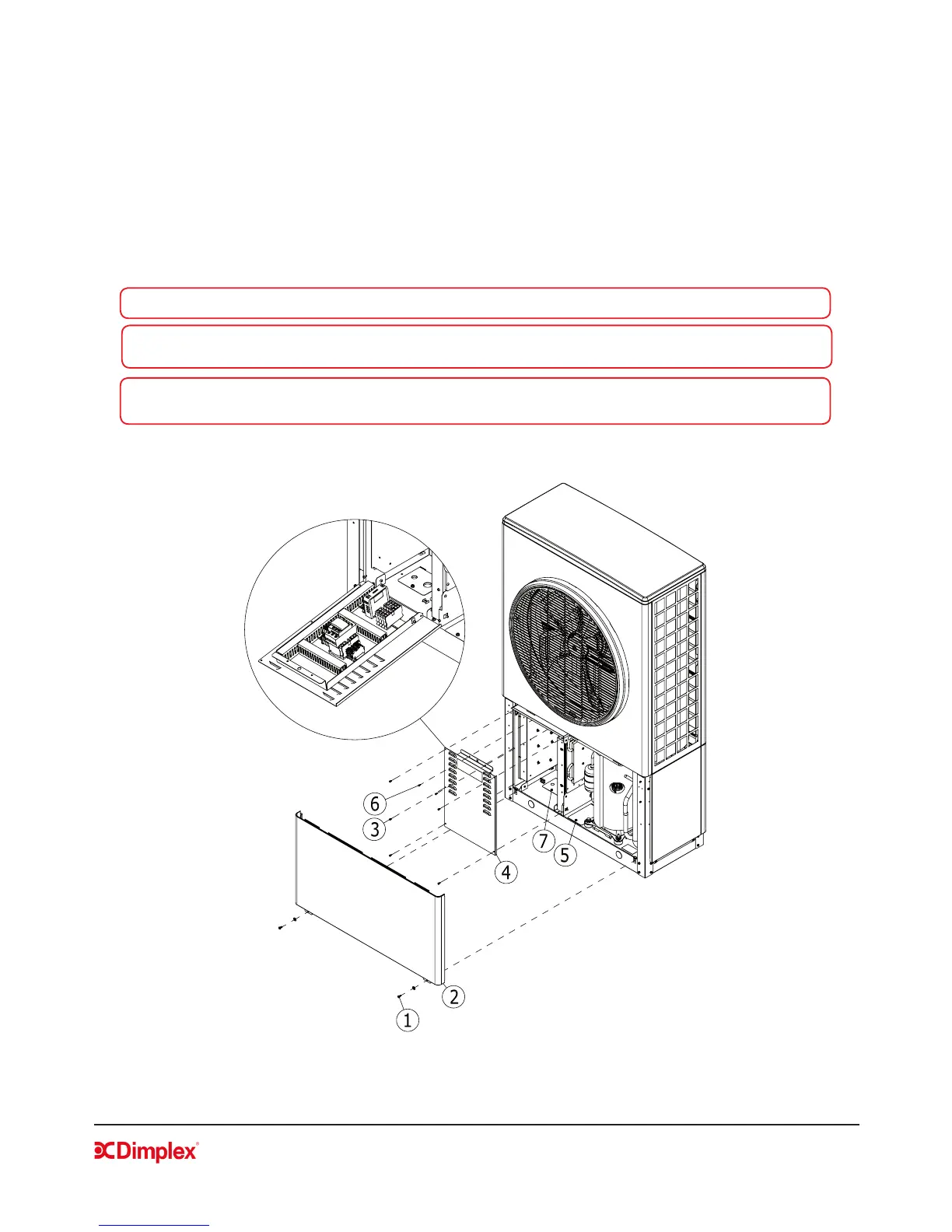
WARNING: Before opening the heat pump, ensure all circuits are isolated.
WARNING: Ensure that the components in the electrical box do not get wet when the electrical box is
opened.
WARNING: The main 230V power cable must be supplied via a suitable sized exterior isolator, lockable
in the OFF position.
4.2.5 Access to Electrical Connections - Opening the heat pump
Figure 9: Access to the electrical box