Millbrook House, Grange Drive, Hedge End, Southampton, SO30 2DF
0844 879 3587
dimplex.co.uk | gdcgroup.co.uk
9
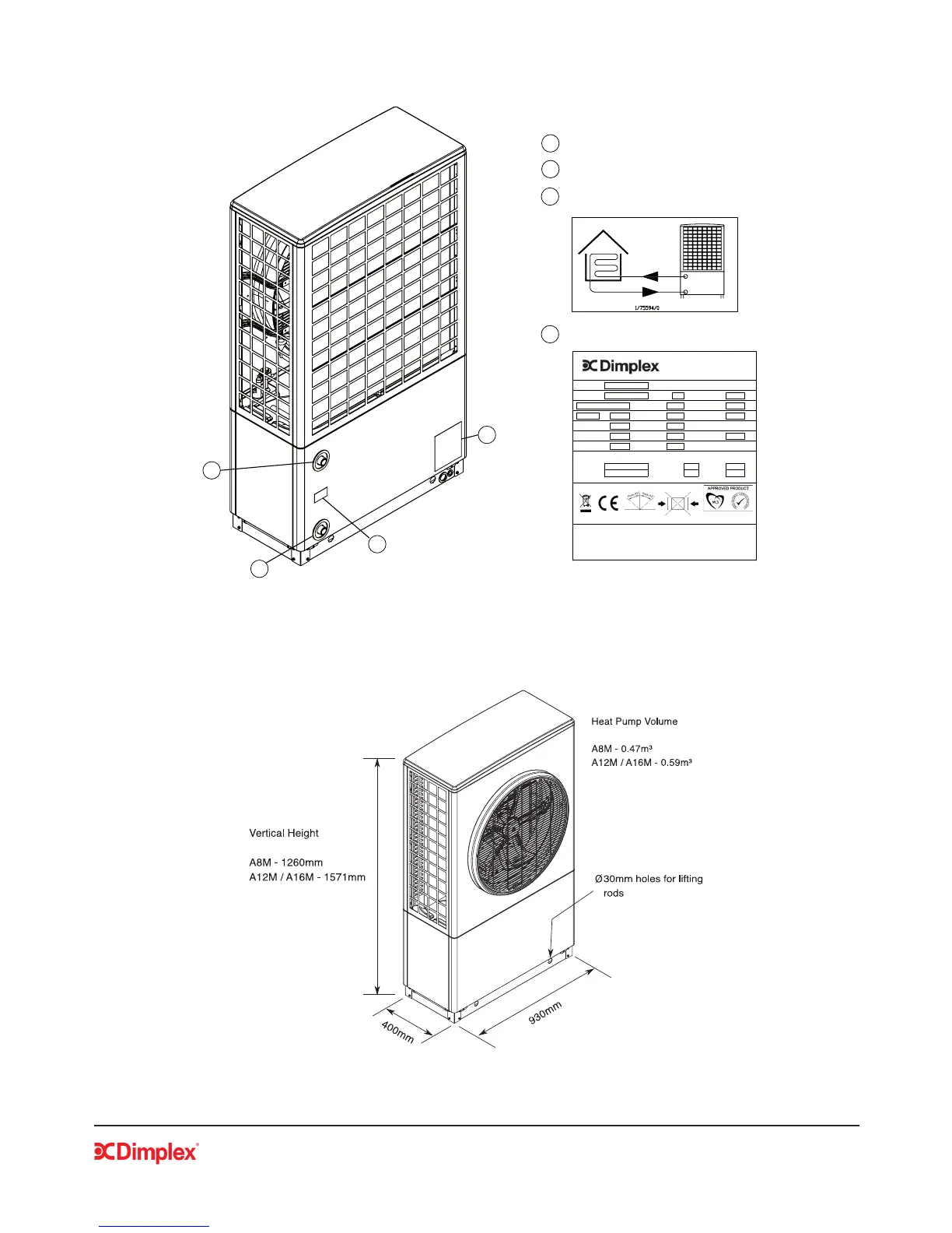
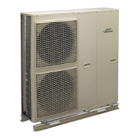
1.5 Heat Pump Labels and Pipe Connections
Figure 2:Heat pump connections and labels
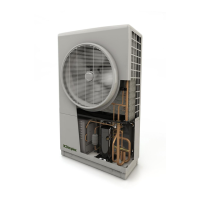
1.6 Heat Pump Dimensions
Figure 3:Heat pump dimensions
1
3
2
4
1
2
Water outlet connection
Water inlet connection
Water connection label
3
Rating label
4
Model:
Serial No. 001
8.0
R410A 2.0 kg
bar
C20 A
C°h/³m0073riA
aPk1.4C°h/³m1.2
Protection: IP 24 kg
12.30 kW COP 4.72
12.90 kW COP 2.20
1/75733/0
The refrigeration cycle is hermetically sealed.
Contains Kyoto-Protocol defined fluorinated greenhouse gases.
All work to be carried out on this unit is to be carried out by a
competent person.
Power Factor
A-2W55
P
Heating
Air to Water Variable Speed Heat Pump
Max Op.
Pressure
Revision:
Single Phase 230V/50Hz
45
kW
Δp
Electrical Power (Max)
P
Heating
A7W35
Heating Water:
EN14511-2 Conditions
A16T
Fabrication Date:
0.99
Fuse Protection
Min.
Flow
T