The property is in Manchester,
England – NHBC recommend -
3C and CIBSE recommend -
2.2C. The design temperature is
therefore -3C.
The properties heat loss is
calculated to be 4.5kW at the
design temperature.
Has been selected at 55C as
radiators are going to be
installed.
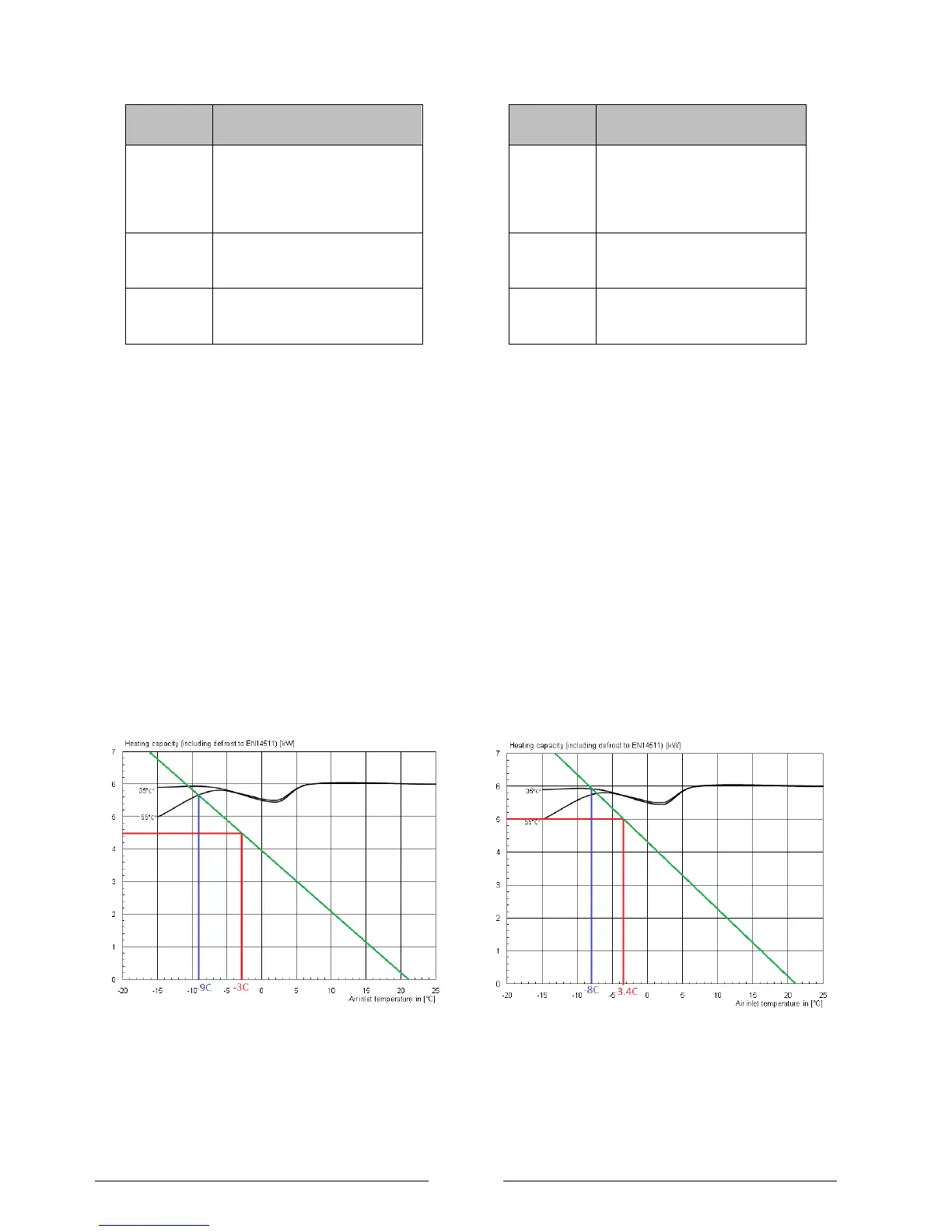
The heat pump is dimensioned on the heat consumption
of the building at the design temperature as shown in
green in Figure 1.
Step 1: The building's heat loss is plotted based upon the
0kW @ 21C and the building‟s calculated heat loss at the
design temperature i.e. 4.5kW @ -3C as shown by the
green line.
Step 2: At the point where the green line crosses the
performance line of the heat pump the blue line can be
drawn to show the external temperature that the heat
pump will be able to match the heat load of the property
which in Figure 1 is -9C.
Step 3: Below external temperatures of -9C the property
will require additional heat. The factory fitted 3kW inline
flow boiler in addition to the 6kW heat pump to gives 9kW
which will support the properties heat load down to the
operating limit of the heat pump which is -20C.
Figure 1: Example heat output curves to EN14511
for the LA 6 MI for a heat loss of 4.5kW at a design
temperature of -3
C.
Sizing example 2
The property is in Birmingham,
England – NHBC recommend
3C and MIS 3005 recommend -
3.4C. The design temperature is
therefore -3.4C.
The properties heat loss is
calculated to be 5kW at the
design temperature.
Has been selected at 35C as
under floor heating is going to be
used.
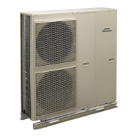
The heat pump is dimensioned on the heat consumption
of the building at the design temperature as shown in
green in Figure 2.
Step 1: The building's heat loss is plotted based upon the
0kW @ 21C and the building‟s calculated heat loss at the
design temperature i.e. 5kW @ -3.4C as shown by the
green line.
Step 2: At the point where the green line crosses the
performance line of the heat pump the blue line can be
drawn to show the external temperature that the heat
pump will be able to match the heat load of the property
which is also 5.9kW at –8C.
Step 3: Below external temperatures of -8C the property
will require additional heat. The factory fitted 3kW inline
flow boiler in addition to the 6kW heat pump to gives 9kW
which will support the properties heat load down to the
operating limit of the heat pump which is -20C.
Figure 2: Example heat output curves for the LA 6 M for a
heat loss of 5.0kW at a design temperature of -1.8C and a the
building heat loading being met down to -15C.