EN-20 452162.66.04 · FD 9606 www.dimplex.de
English
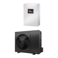
LAW 6IMR - LAW 14ITR
6.2 Control voltage / fuse protection
1~/N/PE 230 V
(50Hz) / C13A
1~/N/PE 230 V
(50Hz) / C13A
1~/N/PE 230 V
(50Hz) / C13A
6.3 Degree of protection according to EN 60 529 indoors/outdoors IP 20 / IP X4 IP 20 / IP X4 IP 20 / IP X4 IP 20 / IP X4
6.4 Starting current limiter Inverter Inverter Inverter Inverter
6.5 Rotary field monitoring Yes Yes Yes Yes
6.6 Starting current A 1,2 1,2 5,9 1,3
6.7 Nominal power consumption at A7/ W35 /
max. consumption
5
6
kW
1,17 / 9,89
7
2,11 / 10,91
7
3,31 / 11,69
7
3,39 / 13,78
7
6.8 Nominal current at A7/W35 / cos A / -- 5,14 / 0,99 9,27 / 0,99 14,54 / 0,99 4,94 / 0,99
6.9 Nominal power consumption at A2/ W35
6
1,41 1,91 3,69 3,50
6.10 Power consumption of compressor protection
(per compressor) W
-- -- -- --
6.11 Power consumption of fan W 124 124 248 248
7 Complies with the European safety regulations
8 8 8 8
8 Additional model features
8.1 Type of defrosting Reverse circulation Reverse circulation Reverse circulation Reverse circulation
8.2 Condensate tray frost protection /
water in device is protected from freezing
9
No / Yes No / Yes Yes/ Yes Yes/ Yes
8.3 Max. operating overpressure (heat source/heat sink) bar 3,0 3,0 3,0 3,0
9 Heat output / coefficient of performance (COP)
9.1 Heat output / coefficient of performance (COP)
5
EN 14511 EN 14511 EN 14511 EN 14511
at A-15 / W35 kW / ---
10
3,6 / 2,3 5,2 / 2,3 10,9 / 2,4 10,8 / 2,4
kW / ---
6
3,6 / 2,3 5,2 / 2,3 10,9 / 2,4 10,8 / 2,4
at A-7 / W35 kW / ---
10
4,2 / 2,8 6,3 / 2,4 13,1 / 2,7 13,9 / 2,9
kW / ---
6
4,2 / 2,8 6,3 / 2,4 13,1 / 2,7 13,9 / 2,9
at A-7 / W55 kW / ---
10
2,9 / 1,8 4,2 / 1,7 9,0 / 1,7 11,3 / 2,1
kW / ---
6
2,9 / 1,8 4,2 / 1,7 9,0 / 1,7 11,3 / 2,1
at A2 / W35 kW / ---
10
4,8 / 3,4 5,3 / 3,6 10,7 / 3,3 10,5 / 3,6
kW / ---
6
4,8 / 3,4 6,2 / 3,2 12,3 / 3,3 11,0 / 3,2
at A7 / W35 kW / ---
10
5,6 / 4,8 5,6 / 4,8 10,2 / 4,4 10,6 / 4,1
kW / ---
6
5,6 / 4,8 9,0 / 4,3 14,6 / 4,4 14,7 / 4,3
at A7 / W45 kW / ---
10
5,4 / 3,4 5,4 / 3,4 9,1 / 3,8 9,8 / 3,7
kW / ---
6
5,4 / 3,4 8,3 / 3,3 14,0 / 3,5 13,9 / 3,3
at A7 / W55 kW / ---
10
5,1 / 2,9 5,1 2,9 8,7 2,9 8,8 2,9
kW / ---
6
5,1 2,9 6,2 2,6 12,9 / 2,9 13,2 / 2,7
at A10 / W35 kW / ---
10
6,0 / 5,1 6,0 / 5,1 10,8 / 4,6 11,3 / 4,5
kW / ---
6
6,0 / 5,1 9,6 / 4,5 14,9 / 4,4 15,7 / 4,3
at A20 / W35 kW / ---
10
7,3 / 5,8 7,3 / 5,8 13,1 / 5,7 13,9 / 5,5
kW / ---
6
7,3 / 5,8 10,8 / 5,3 18,8 / 5,7 22,3 / 5,1
at A20 / W55 kW / ---
10
5,7 / 3,4 5,7 / 3,4 10,6 / 3,6 10,8 / 3,7
kW / ---
6
5,7 / 3,4 8,4 / 3,2 16,9 / 3,7 16,2 / 3,6
9.2 Cooling capacity / coefficient of performance (COP)
at A27 / W7 kW / ---
6
6,5 / 3,3 6,5 / 3,3 12,4 / 3,1 12,9 / 3,0
at A27 / W18 kW / ---
6
8,7 / 4,2 8,7 / 4,2 16,4 / 3,8 17,1 / 3,7
at A35 / W7 kW / ---
6
6,2 / 2,6 6,2 / 2,6 11,8 / 2,5 12,3 / 2,5
at A35 / W18 kW / ---
6
9,0 / 3,4 9,0 / 3,4 14,0 / 3,1 15,5 / 3,3
1. The specified sound levels apply if the supporting feet (available as an option) are not used. If the supporting feet are used, the level can increase by up to 3 dB (A).
2. The specified sound pressure level corresponds to the operating noise of the heat pump in heating operation with a flow temperature of 35°C
The specified sound pressure level represents the free sound area level. The measured value can deviate by up to 16 dB(A), depending on the installation location.
3. Please note that additional space is required for pipe connections, operation and maintenance.
4. Delivery state 6 kW
5. This information shows the size and performance of the system in accordance with EN 14511. For economical and energy-related considerations, the bivalence point and control must
be taken into account. These figures are only achieved with clean heat exchangers. Instructions for care, commissioning and operation can be found in the relevant sections of the
installation and operation instructions. The specified values have the following meaning, e.g. A7 / W35: Heat source temperature 7 °C and heating water flow temperature 35 °C.
6. Maximum heating/cooling outpu
7. Max. intake incl. pipe heating and immersion heater (state of supply)
8. See CE declaration of conformity
9. The heat circulating pump and the heat pump controller must always be ready for operation.
10.COP-optimised operation