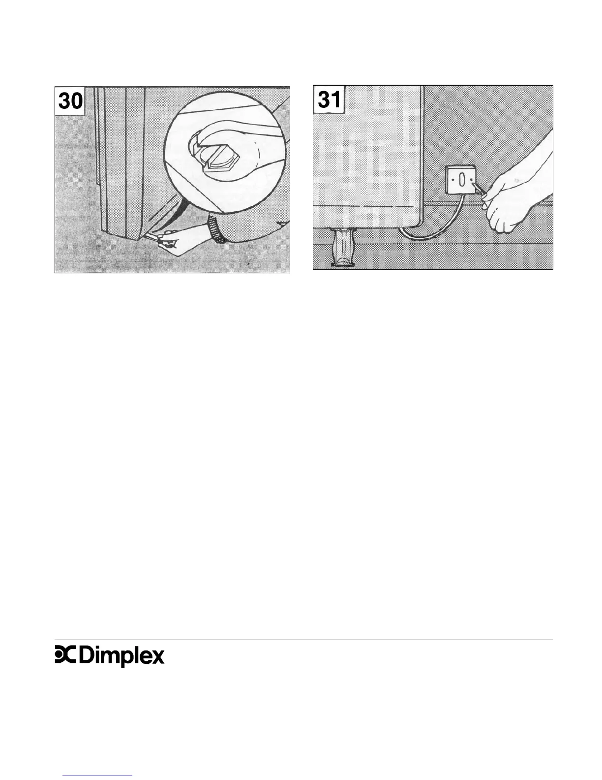
30. Replace the two front panel securing screws removed
in operation 15. A small mirror on the fl oor under the
heater will help location of the threaded holes in the base.
These should be tightened using an 8mm AF socket or
open ended spanner.
Ensure all screws have been fully tightened.
31. Ensuring the electricity supply is disconnected,
connect the free end of the mains cable to a suitable
double-pole switch adjacent to the appliance -
reinstate the electricity supply.
NOTE: The double pole switch must have a contact
separation of at least 3mm in all poles.
© GDC Group Ltd. All rights reserved.
Material contained in this publication may not be reproduced in whole or in part, without prior permission in writing.
A division of the GDC Group Ltd, Millbrook House, Grange Drive, Hedge End, Southampton SO30 2DF
Dimplex UK Limited,
Millbrook House,
Grange Drive,
Hedge End,
Southampton, SO30 2DF.
Tel: 0845 600 5111
Fax: 01489 773 050
Web-site www.dimplex.co.uk
 Loading...