INSTALLATION INSTRUCTIONS
PREPARATION
The heater will arrive
separately from its
storage bricks, the
following bricks will
be required:
Model 706N - 4 bricks
Model 712N - 8 bricks
Model 718N - 12 bricks
Model 724N - 16 bricks
Only heat resisting cable (min. rating T85) should be
used. The wires in the mains cable will be coloured as
follows:-
GREEN & YELLOW - EARTH
BLUE - NEUTRAL
BROWN - LIVE
SUGGESTED FIXINGS
SOLID BRICK/BLOCK: No. 10 Size plastic inserts,
8mm drill bit. Drill hole 15mm deeper than plastic insert
length.
PLASTERBOARD - If possible locate studding and use
No. 10 woodscrews directly into the wood, otherwise
M5 rawlplug intersets are suitable.
NOTE: FOR OTHER WALL TYPES (e.g. Timber frame
and hollow concrete) SEEK SPECIALIST ADVICE.
FIXING ASSEMBLY
ENSURE THAT FIXING KIT AND FEET HAVE BEEN
LOCATED BEFORE DISPOSING OF PACKAGING.
Fit the feet with the open end of the foot to the front of
the heater. Secure each foot using two taptite screws
provided.
2.
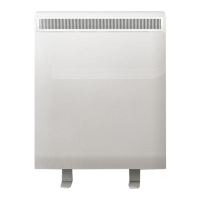
Place the heater on its feet and in the desired position
against the wall. Ensure the heater is based on a fi rm
level surface at least 75mm from any end wall and at least
250mm below any shelf or similar projection. Cut away any
gripper rod or carpet which would prevent the heater sitting
fi rmly on the fl oor.
3.
Mark the position of the two outside corners of the wall
bracket with the heater pushed tight against the wall.
Remove the wall bracket from the heater by removing
the screw at each end. Place the heater to one side and
reposition the bracket against the wall using the corner marks
for alignment.
Four fi xing positions must be chosen for the 724N, three for
the 718N and two for the 712N and 706N. Mark the positions
for the fi xing holes - two at the extreme ends and the others
spaced evenly between them. Remove the bracket from
the wall, drill the holes in the positions marked, and insert
suitable fi xings previously described. Secure the wall bracket
to the wall.
4.
4.
If mains connection is to be made from the left side, at
this point the mains lead must be secured to the back of
the heater using ties provided in the fi xing kit.
5.
5.
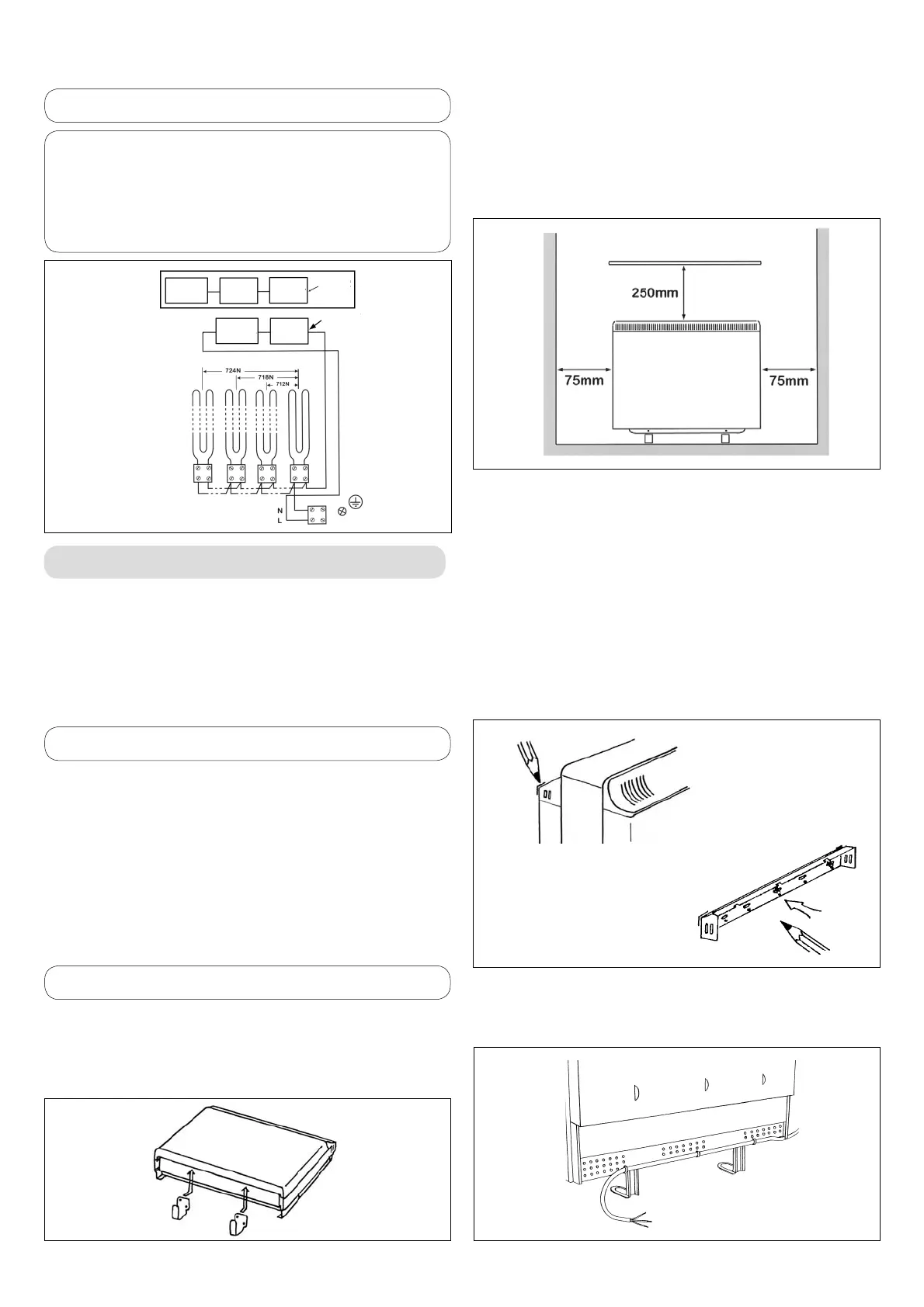
WARNING - This appliance must be earthed
2.
1.
3.
LIMIT STAT
CUT OUT
ROOM
STAT
XMS712/718
MODELS
ONLY
XMS MODELS
ONLY
LIMIT STAT
AND
CUT OUT
ROOM
STAT
CIRCUIT
DIAGRAM
STORAGE ELEMENTS