Installation Diagrams - Diagram 12. 110°, 118.7°, & 119° (DISH 500+) 3 - 15
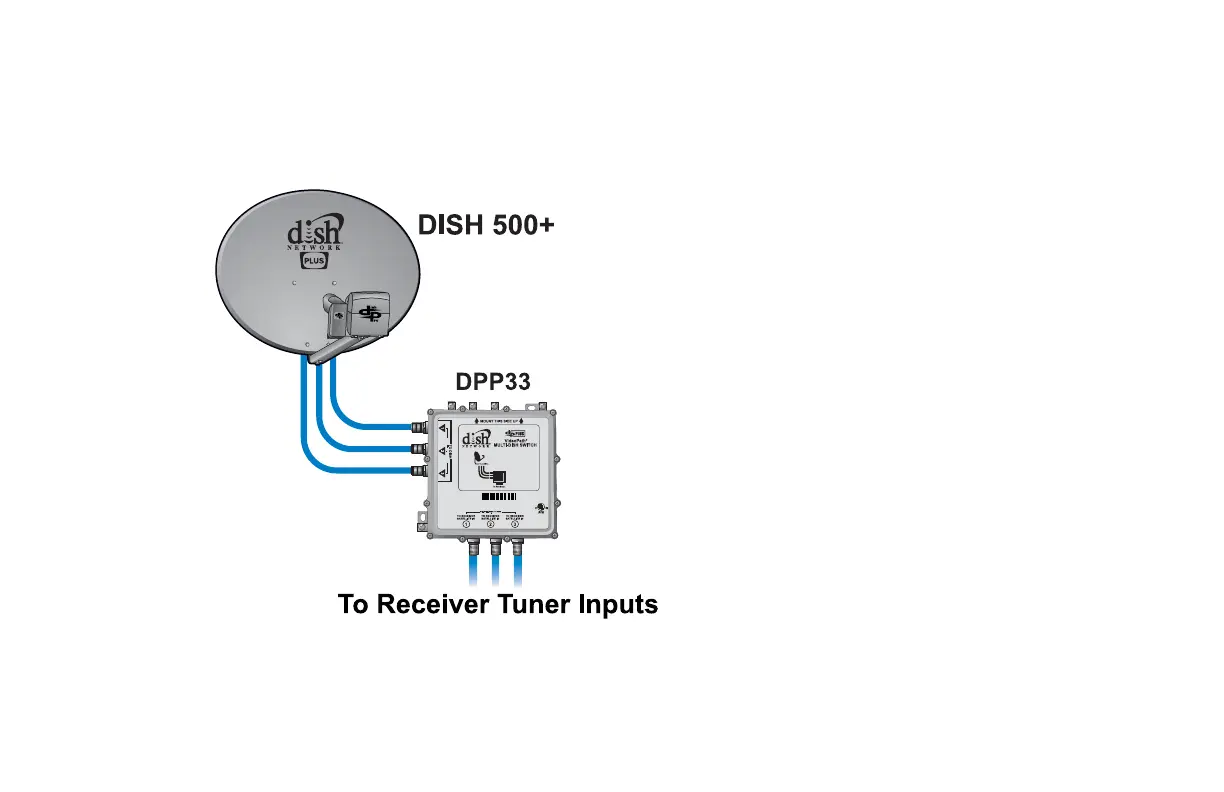
Diagram 12. 110°, 118.7°, & 119° (DISH 500+)
Uses DP 500+ LNBF Assembly and DISH Pro Plus 33
This device complies with part 15 of the FCC Rules. Operation is subject to the following two
conditions: (1) This device may not cause harmful interference, and (2) this device must accept
any interference received, including interference that may cause undesired operation.
Grounding wire size:
Copper wire-8-14 AWG
Copper coated steel
wire-17 AWG
MADE IN
USA
10.5-21V 365mA PER PORT
MODEL DPP33
145574
• Single-cable/dual-tuner receiver
installations require a DP Plus
Separator.
• A legacy receiver installation must also
include at least one DP or DP Plus
receiver.
• A DP34 Switch is also an option if you
don’t require a single-cable/dual-tuner
installation. See the DP34 Switch for
connectivity details.
• Grounding according to the National
Electric Code (NEC) and all local
electrical codes is required.