14 / 16
Controller
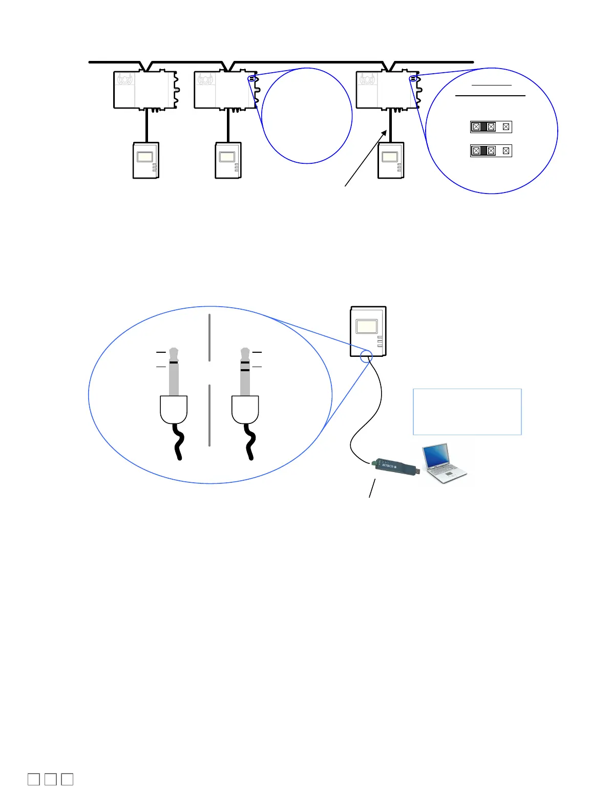
Bus Network Topology: 22AWG (0.65mm) Unshielded Twisted Pair Network Cable
Cat 5e Cable Subnetwork Bus Provides:
· Room Device Data communication
· LONWORKS Network when Net to Subnet
Port Settings jumpers are Enabled
E
D
Enable
Disable
For a Few
Controllers ONLY:
Standard Net to
Subnet Port
Settings:
DISABLED - this
is the factory
default setting
Communicating Sensor
Net to Subnet Port Settings
Optionally Enabled
Figure16: LONWORKS Network: Bus Topology
To temporarily access the LONWORKS LAN for commissioning and maintenance purposes, connect a LONWORKS USB network interface to the audio plug
port located on the lower edge of the Allure EC-Smart-Vue sensor. Wire a standard ⅛” (3.5 mm) three-conductor (stereo jack) or two-conductor (mono
jack) as shown below.
- Temporary
Commissioning and
Maintenance
Connection
LON USB Network
Interface
To LON USB
Network Interface
LON1
LON2
LAN Access
Connector
LON1
LON2
Mono Jack Stereo Jack
OR
LAN Access
Connector
Figure17: ⅛” (3.5 mm) Stereo or Mono Jack Connection for a LONWORKS Network Interface
 Loading...