7 / 16
Controller:
ECB-600
ECL-600
Cat 5e Cable Subnetwork Bus
Inside
Controller
Back of
Allure EC-Smart-Vue
Sensor
EOL set to ON
at the last
sensor at the
end of the Bus
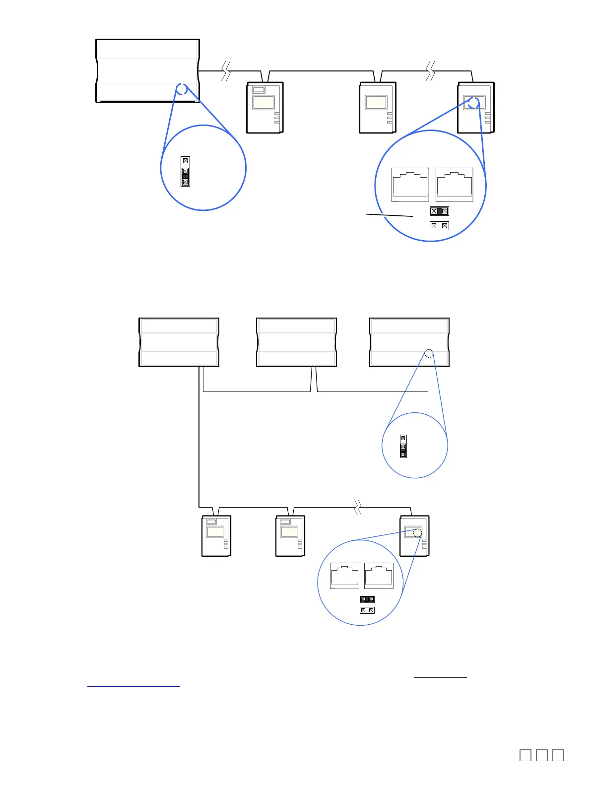
For the controller, set the
Subnetwork EOL to ON
Figure9: Setting the EOL Terminations on the Allure EC-Smart-VueSensor for ECB-600 or ECL-600 Seriescontrollers
When ECx-400 Series I/O Extension Modules are installed with an ECB-600 or ECL-600 Series controller and with Allure Series Communicating Sen-
sors, only the EOL terminations on the last I/O Extension Module and the last Allure Series Communicating Sensor are set to ON. The ECB-600 /
ECL-600 and all other I/O Extension Modules and Allure Series Communicating Sensor s must have their EOL terminations set to OFF.
Typical Compatible
Controller
I/O Extension Modules
ECx-4xx
ECx-4xx
I/O Extension Modules 2 - Wire Shielded
- Last daisy-chained I/O Extension Module:
EOL Jumper is ON
- All other I/O Extension Modules:
EOL Jumpers are OFF
- Last daisy-chained Communicating Sensor:
EOL Jumper is ON
- All other Communicating Sensors:
EOL Jumpers are OFF
Communicating Sensor Sub-Network Bus
- Cat 5e Cable with RJ-45 Connectors
Figure10: Setting the EOL Terminations on the ECx-400 SeriesSubnetwork Bus when Allure EC-Smart-VueSensors are used
ECx-400 Series devices and Allure EC-Smart-Vue sensors are factory-set with the EOL set to OFF by default.
If inserting multiple wires in the terminals, ensure to properly twist wires together prior to inserting them into the terminal connectors.
For more information and detailed explanations on network topology and wire length restrictions, refer to the Network Guide, which can be downloaded
from our website
www.distech-controls.com
.
 Loading...