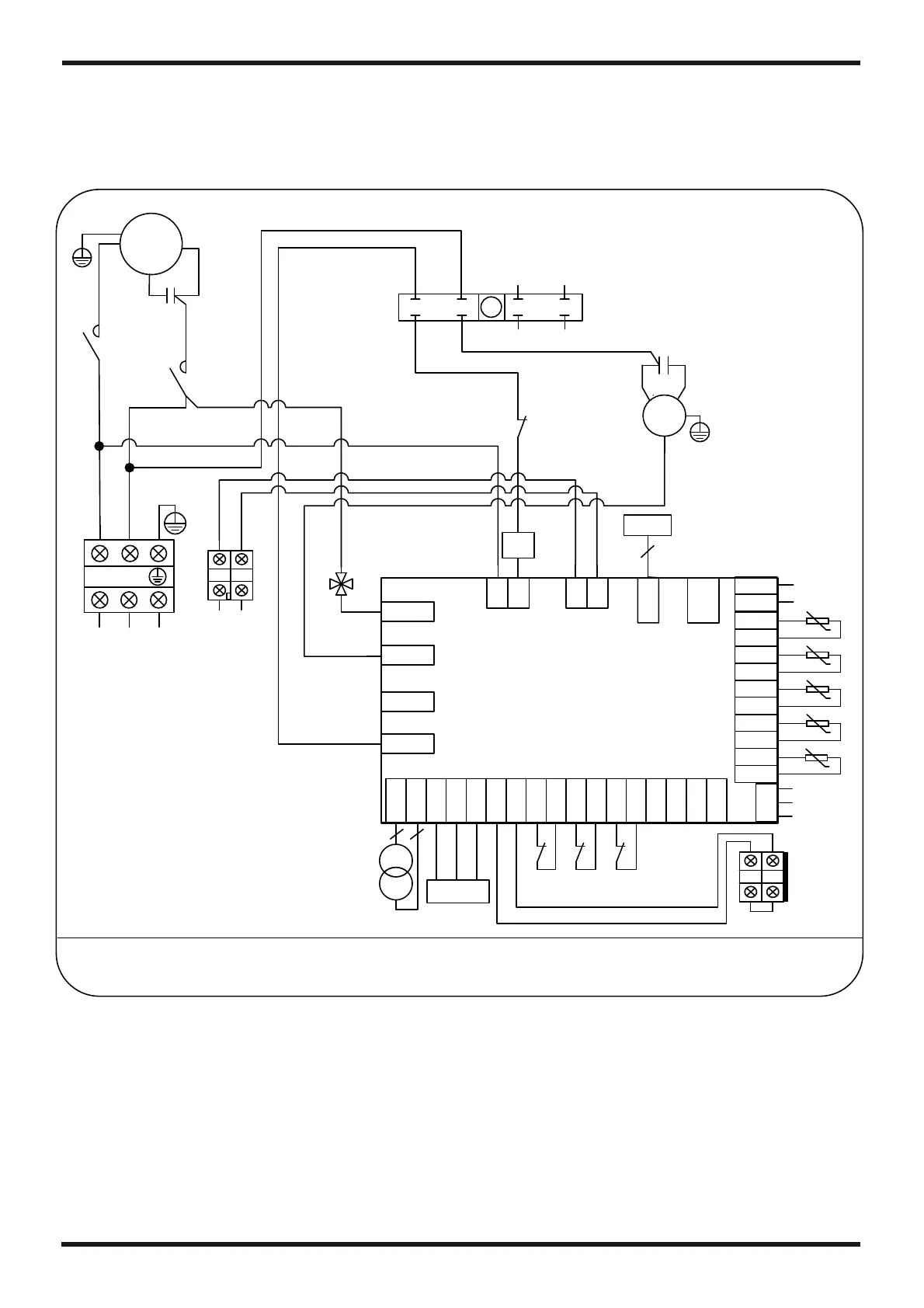
Appendix 5: Circuit diagram of the unit
6. APPENDIX
21
PASRW030
CC
COMP
CS
CR
BLK
WHT
RED
CR
CS
CC
TO POWER
SUPPLY
208-230V~/60HZ
CC
1
3
24
5
6
7
8
01
L2
L21
L2
Controller
KM1
FM
C2
BLK
BLU
RED
L2
TC
12V
HP12
L1 L2
BLK
WHT
L1
L1
L1
L22
L2L2
L2
L2
C1
34
3
4
REMOTE IN
3
4
LP
FS
FS
LP
LP
FS
HP11
HP11
HP11
t
5K
t
5K
t
5K
t
5K
IT
IT
OT
OT
AT
AT
CT
CT
OUT3
OUT4
OUT5
AC-N
3
4
3
4
CN19
GND
AI05
GND
AI04
GND
AI03
GND
AI02
GND
CN1
CN2
12V
NET
GND
DI01
GND
DI02
GND
DI03
GND
DI04
GND
DI05
GND
AI01
GND
DI06
GND
CN6
AI06
CN16
GND
+5V
OUT1 OUT2
PC1001
BLU
Y/G
BRN
22
K1
Y/G
L1 L2
KM1
KM1
L22
L2
L2
L2
L1
L2
4V
L2
4V
L2
RED
C1
Y/G
Y/G
Dry Contact
12
1
2
1
2
t
5K
SUT
SUT
4V˖4 way valve
AT˖Ambient temperature
FM˖Fan motor
IT˖Inlet water temperature
LP˖Low pressure protection
OT˖Outlet water temperature
FS˖Flow switch
HP12˖High pressure protection(4.4MPa)
KM1˖Contactor of compressor
COMP˖Compressor
HP11˖High pressure protection(4.0MPa)
CT˖Coil temperature
TC˖Transformer
SUT˖Suction temperature
EEV˖Electronic expansion valve
EEV
5