13
DITEC S.P.A - IP1580 30/06/99 - CS61/CS61E
WARNING: Link up all N.C. contacts (if not used) by means of jumpers.
The terminal bearing the same number are equivalent.
ENGLISH
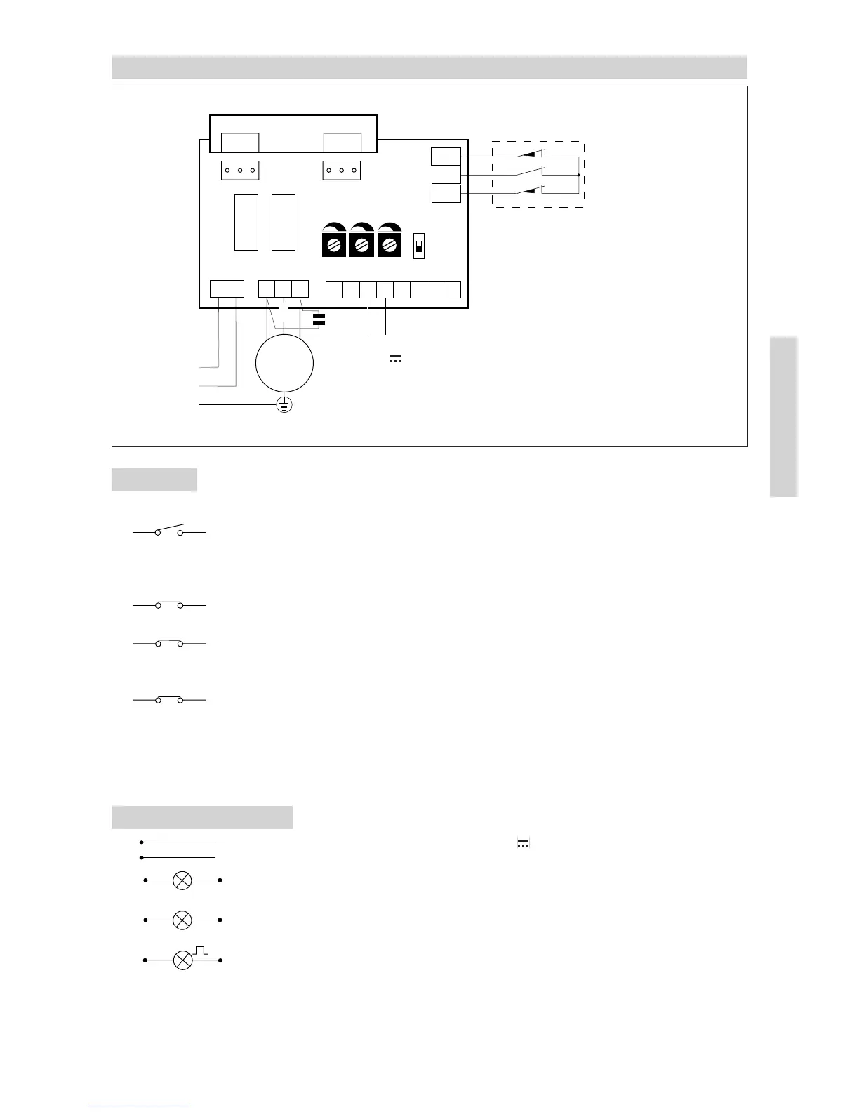
4. ELECTRICAL CONNECTIONS CS61E
4.1 Controls
CONTACT FUNCTION DESCRIPTION
15(N.O.) STEP BY STEP With TC at maximum: “open-stop-close” sequence.
With TC not at maximum: “open-close/automatic
closure” sequence. The closing control can operate
when the gate is standing opened.
16(N.C.) STOP SAFETY It stops and/or prevents any movement.
CONTACT
18(N.C.) REVERSAL SAFETY Reverses movement (re-opens) during closing.
CONTACT When door is not moving, inhibits all operation.
19(N.C.) EMERCENCY By opening the 1-9 contact the gate stops or remains
STOP still and the automatic closing is disabled.
REMOTE CONTROL STEP BY STEP It has the same function as the 1-5 control.
Parallel connection This model does not permit the running of two motors
of automatic controls in parallel.
4.2. Output and accessories
1 + Accessories power supply. 24V / 0.15A (nominal) / 0.3 A (peak) output
0- for powering of external accessories including gate state lamp.
1 11 Lamp (24 V / 1.5 W) gate open with DIP1 ON, closed gate lamp with
DIP1 OFF.
1 12 Lamp (24 V / 1.5 W) gate close with DIP1 OFF, open gate lamp with
DIP1 ON.
W N Flashing light. 230 V~/ 100 W max. output. It is lighting during the opening
and closing operation. With automatic closure mode the flashing begins
3 s before the end of the setted time of TC, with TC lesser 3 s the flashing
lasts as long as the break time.
F1
F2
Q.E. D61
LN
UWV
1211015689
230 V~
M
1 ~
FC2
FC1
COM
16 µF
RF TC R1
DIP1
Limit switch
Release micro
Limit switch
ON
OFF
+
-
24 V / 0.15 A
F1 = F5 A line
F2 = F315 mA accessories
CONTROL BOARD
com