Displays of series DT-203NN, DT-105NN and DT-110NN
3 INSTALLATION
The installation of the DT-203, DT-105 and DT-110 is not difficult but some important
considerations must be taken into account.
It must not be anchored to places subjected to vibrations, nor should it be installed in
places which generally surpass the limits specified in the display characteristics, both in terms of
temperature and humidity.
The degree of protection of displays DN-109, DN-119, DN-129 and DN-189 is IP41, it
means that are protected against the penetration of strange solid objects greater than 1 mm,
and against the vertical rain drops. DN-129f is IP54, which mean that is protected against the
rain water. The degree of protection of displays DN-109e, DN-119e and DN-189e are IP65, it
means that are completely protected against the dust, and water jets.
Displays DT-203, DT-105 and DT-110, should not be installed in places with illumination
level higher than 1000 lux. Neither should the display be placed in direct sunlight as visibility
would be lost. Displays DT-105h and DT-110h can be read in sunlight.
In the electrical installation, proximity to high-current lines and high voltage lines must
be avoided, as well as proximity to High Frequency generators and U/F converters for motors.
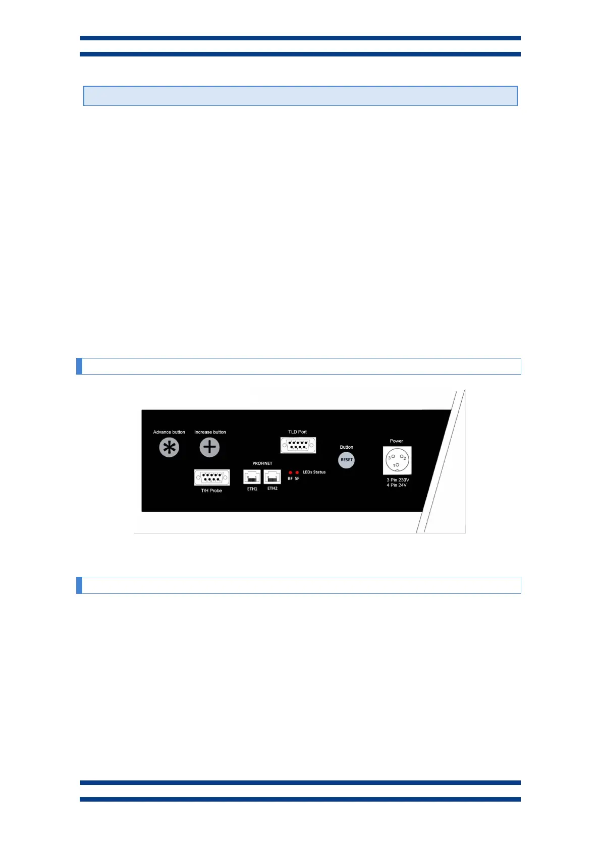
3.1 Equipment interfaces
3.2 Power supply.
The power supply must be from 100 to 240 VAC, 50/60 Hz or 24VDC (18-36) 24V
option.
The external power supply conductor section must be selected according to the
consumption and the ground conductor must have a minimum section of 1.5 mm².
The power supply connector for 220VAC has 3 contacts and is placed in the lower part
of the unit. Connect the power wires following the schema below
The power supply connector for 24VDC has 4 contacts and is placed in the lower part of
the unit. Connect the power wires following the schema below
Fig. 2 Connectors and push buttons. Exact positions depend on the model.
 Loading...