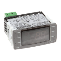
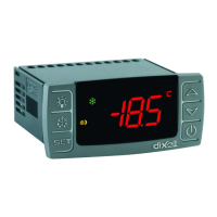
dIXEL
Installing and Operating Instructions
1592026020
1592026020 XW60K GB R1.0 22.02.2008.doc XW60K 51
Power supply: 230Vac or. 110Vac
± 10% or 24Vac
Power absorption: 10VA max.
Inputs: 4 NTC probes
Digital inputs: 1 free voltage
Relay outputs: Total current on loads MAX. 20A
compressor: relay SPST 20(8) A, 250Vac
fan: relay SPST 8(3) A, 250Vac
defrost: relay SPST 16(5) A, 250Vac
light (oA3): relay SPST 16(5) A, 250Vac
Serial output : TTL standard.
Communication protocol: Modbus - RTU
Data storing: on the non-volatile memory (EEPROM).
Kind of action: 1B.
Pollution grade: normal
Software class: A.
Operating temperature: 0÷60 °C.
Storage temperature: -25÷60 °C.
Relative humidity: 20
÷85% (no condensing)
Measuring and regulation range: NTC probe: -40÷110°C (-58÷230°F)
Resolution: 0,1 °C or 1°C or 1 °F (selectable).
Accuracy (ambient temp. 25°C): ±0,5 °C ±1 digit
14. CONNECTIONS
14.1 XW60K
15. Default setting values
Label Name Range Default Level
REGULATION
Set Set point LS÷US
-5.0 - - -
Hy Differential 0,1÷25,5 °C / 1÷45°F
2.0 Pr1
LS Minimum set point -50,0°C÷SET / -58°F÷SET
-50.0 Pr2
US Maximum set point SET ÷ 110°C / SET ÷ 230°F
110 Pr2
Ot Thermostat probe calibration
-12÷12°C /-120÷120°F
0.0 Pr1
P2P Evaporator probe presence n=not present; Y=pres.
Y Pr1
OE Evaporator probe calibration
-12÷12°C /-120÷120°F
0.0 Pr2
P3P
1
Third probe presence (1st cond.
probe)
n=not present; Y=pres.
n Pr2
O3
1
Third probe calibration
-12÷12°C /-120÷120°F
0 Pr2
P4P Fourth probe presence (2nd cond.
probe)
n=not present; Y=pres.
n Pr2
O4 Fourth probe calibration
-12÷12°C /-120÷120°F
0 Pr2
OdS Outputs activation delay at start up 0÷255 min.
0 Pr2
AC Anti-short cycle delay 0÷30 min.
1 Pr1
Ac1 Second compressor delay 0÷255s
5 Pr2
rtr P1-P2 percentage for regulation 0 ÷ 100 (100=P1 , 0=P2)
100 Pr2
CCt Compressor ON time during fast
freezing
0 ÷ 23h 50 min.
0.0 Pr2
CCS Set point for continuous cycle (-55.0÷150,0°C)
-5 Pr2
COn Compressor ON time with faulty probe 0÷255 min.
15 Pr2
COF Compressor OFF time with faulty
probe
0÷255 min.
30 Pr2
DISPLAY
CF Temperature measurement unit °C ÷ °F °C Pr2
rES Resolution (integer/decimal point) in ÷ de dE Pr1
rEd Remote display P1 ÷ 1r2 P1 Pr2
dLy Display temperature delay 0 ÷ 20.0 min (10 sec.)
0 Pr2
dtr P1-P2 percentage for disply 1 ÷ 99
50 Pr2
DEFROST
tdF Defrost type EL, in
EL Pr1
dFP Probe selection for defrost termination nP; P1; P2; P3; P4
P2 Pr2
dtE Defrost termination temperature -50,0÷110°C / -58÷230°F 8.0 Pr1
IdF Interval between defrost cycles 1÷120h 6 Pr1
MdF (Maximum) length for 1° defrost 0÷255 min. 30 Pr1
dSd Start defrost delay 0÷99min
0 Pr2
dFd Displaying during defrost rt, it, SEt, dEF, dEG
it Pr2
dAd MAX display delay after defrost 0÷255 min.
30 Pr2
Fdt Draining time 0÷60 min.
0 Pr2
dPO First defrost after start up n ÷ y
n Pr2
dAF Defrost delay after fast freezing 0 ÷ 23h 50 min.
0.0 Pr2
FANS
FnC Fans operating mode C-n, C-y, O-n, O-y
o-n Pr1
Fnd Fans delay after defrost 0÷255 min.
10 Pr1
Fct Differential of temperature for forced
activation of fans
0÷50°C
10 Pr2
Label Name Range Default Level
FSt Fans stop temperature -50,0÷110°C / -58÷230°F
2 Pr1
Fon Fan on time with compressor off 0÷15 (min.)
0 Pr2
FoF Fan off time with compressor off 0÷15 (min.)
0 Pr2
FAP Probe selection for fan management nP; P1; P2; P3; P4
P2 Pr2
AUXILIARY THERMOSTAT
ACH Kind of action for auxiliary relay CL; Ht
cL Pr2
SAA Set Point for auxiliary relay -50,0÷110°C / -58÷230°F
0,0 Pr2
SHy Differential for auxiliary relay 0,1÷25,5 °C / 1÷45°F
2,0 Pr2
ArP Probe selection for auxiliary relay nP / P1 / P2 / P3
nP Pr2
Sdd Aux.output working during defrost n, y
n Pr2
ALARMS
ALP Probe setting for temperature alarm P1÷P4
P1 Pr2
ALC Temperature alarms configuration rE÷Ab
rE Pr2
ALU MAXIMUM temperature alarm -50,0÷110°C / -58÷230°F
10,0 Pr1
ALL minimum temperature alarm -50,0÷110°C / -58÷230°F
10,0 Pr1
AFH Temperature alarm and fan differential 0,1÷25,5 °C / 1÷45°F
2,0 Pr2
ALd Temperature alarm delay 0÷255 min.
15 Pr2
dAO Delay of temperature alarm at start up 0 ÷ 23h 50 min.
1,3 Pr2
AP2 Probe for temperat. alarm of
condenser
nP; P1; P2; P3; P4
P4 Pr2
AL2 Condenser for low temperat. alarm (-55 ÷ 150°C) (-67÷ 302°F)
-40 Pr2
AU2 Condenser for high temperat. alarm (-55 ÷ 150°C) (-67÷ 302°F)
110 Pr2
AH2
Differ. for condenser temp. alar.
recovery
[0,1°C ÷ 25,5°C] [1°F ÷ 45°F]
5 Pr2
Ad2 Condenser temperature alarm delay 0 ÷ 254 (min.) , 255=nU
15 Pr2
dA2
Delay of cond. temper. alarm at start
up
0.0 ÷ 23h 50’
1,3 Pr2
bLL
Compr. off for condenser low
temperature alarm
n(0) - Y(1)
n Pr2
AC2
Compr. off for condenser high
temperature alarm
n(0) - Y(1)
n Pr2
AUXILIARY OUTPUT
tbA Alarm relay disabling n=no; y=yes
y Pr2
oA3 Fourth relay configuration ALr = alarm; dEF = do not select it;
Lig =Light; AUS =AUX; onF=always
on; Fan= do not select it; db = do
not select it; dF2 = do not select it
Lig Pr2
AoP Alarm relay polarity (oA3=ALr) oP; cL
cL Pr2
DIGITAL INPUT
i1P Digital input polarity oP=opening;CL=closing
cL Pr1
i1F Digital input configuration
EAL, bAL, PAL, dor; dEF; Htr, AUS
dor Pr1
did Digital input alarm delay 0÷255min
15 Pr1
Nps Number of activation of pressure
switch
0 ÷15
15 Pr2
odc Compress and fan status when open
door
no; Fan; CPr; F_C
F-c Pr2
rrd Regulation restart with door open
alarm
n – Y
y Pr2
HES Differential for Energy Saving -30°C÷30°C; -54°F÷54°F
0 Pr2
OTHER
PbC Kind of probe
Ptc; ntc
1 Pr2
Adr Serrial address
1÷247
ntc Pr1
onF on/off key enabling nu, oFF; ES
oFF Pr2
dP1 Room probe display --
- Pr1
dP2 Evaporator probe display --
- Pr1
dP3 Third probe display --
- Pr1
dP4 Fourth probe display --
- Pr1
rSE Current set point -
Pr1
rEL Software release - - -
1,1 Pr2
Ptb Map code - - -
- Pr2
dIXEL S.p.a.
Z.I. Via dell’Industria, 27 - 32010 Pieve d’Alpago (BL) ITALY
tel. +39 - 0437 - 98 33 - fax +39 - 0437 - 98 93 13
http://www.dixell.com
E-mail: dixell@dixell.com
 Loading...