dIXEL
Installing and Operating Instructions
1592020570
1592020570 XR70CX RTC GB r1.0 28.05.2008.doc XR70CX 4/5
12.1 PROBE CONNECTION
The probes shall be mounted with the bulb upwards to prevent damages due to casual liquid
infiltration. It is recommended to place the thermostat probe away from air streams to correctly
measure the average room temperature. Place the defrost termination probe among the evaporator
fins in the coldest place, where most ice is formed, far from heaters or from the warmest place during
defrost, to prevent premature defrost termination.
13. HOW TO USE THE HOT KEY
13.1 HOW TO PROGRAM A HOT KEY FROM THE INSTRUMENT (UPLOAD)
1. Program one controller with the front keypad.
2. When the controller is ON
, insert the “Hot key” and push o key; the "uPL" message
appears followed a by flashing “End”
3. Push “SET” key and the End will stop flashing.
4. Turn OFF
the instrument remove the “Hot Key”, then turn it ON again.
NOTE: the “Err” message is displayed for failed programming. In this case push again o key if you
want to restart the upload again or remove the “Hot key” to abort the operation.
13.2 HOW TO PROGRAM AN INSTRUMENT USING A HOT KEY
(DOWNLOAD)
1. Turn OFF the instrument.
2. Insert a programmed “Hot Key” into the 5 PIN receptacle and then turn the Controller ON.
3. Automatically the parameter list of the “Hot Key” is downloaded into the Controller memory,
the “doL” message is blinking followed a by flashing “End”.
4. After 10 seconds the instrument will restart working with the new parameters.
5. Remove the “Hot Key”..
NOTE the message “Err” is displayed for failed programming. In this case turn the unit off and then
on if you want to restart the download again or remove the “Hot key” to abort the operation.
14. ALARM SIGNALS
Message Cause Outputs
“P1” Room probe failure Compressor output acc. to par. “Con” and “COF”
“P2” Evaporator probe failure Defrost end is timed
“P3” Third probe failure Outputs unchanged
“P4” Fourth probe failure Outputs unchanged
“HA” Maximum temperature alarm Outputs unchanged.
“LA” Minimum temperature alarm Outputs unchanged.
"HA2" Condenser high temperature It depends on the “Ac2” parameter
"LA2" Condenser low temperature It depends on the “bLL” parameter
“dA” Door open Compressor and fans restarts
“EA” External alarm Output unchanged.
“CA” Serious external alarm (i1F=bAL) All outputs OFF.
“CA” Pressure switch alarm (i1F=PAL) All outputs OFF
“rtc” Real time clock alarm Alarm output ON; Other outputs unchanged;
Defrosts according to par. “IdF” Set real time clock
has to be set
rtF Real time clock board failure Alarm output ON; Other outputs unchanged;
Defrosts according to par. “IdF” Contact the
service
14.1 ALARM RECOVERY
Probe alarms P1”, “P2”, “P3” and “P4” start some seconds after the fault in the related probe; they
automatically stop some seconds after the probe restarts normal operation. Check connections
before replacing the probe.
Temperature alarms “HA”, “LA” “HA2” and “LA2” automatically stop as soon as the temperature
returns to normal values.
Alarms “EA” and “CA” (with i1F=bAL) recover as soon as the digital input is disabled.
Alarm “CA” (with i1F=PAL) recovers only by switching off and on the instrument.
14.2 OTHER MESSAGES
Pon
Keyboard unlocked.
PoF
Keyboard locked
noP
In programming mode: none parameter is present in Pr1
On the display or in dP2, dP3, dP4: the selected probe is nor enabled
15. TECHNICAL DATA
Housing: self extinguishing ABS.
Case: XR70CX frontal 32x74 mm; depth 60mm;
Mounting: XR70CX panel mounting in a 71x29mm panel cut-out
Protection: IP20; Frontal protection: XR70CX IP65
Connections: Screw terminal block ≤ 2,5 mm
2
wiring.
Power supply: according to the model: 12Vac/dc, ±10%; 24Vac/dc, ±10%; 230Vac ±10%,
50/60Hz, 110Vac ±10%, 50/60Hz
Power absorption: 3VA max
Display: 3 digits, red LED, 14,2 mm high; Inputs: Up to 4 NTC or PTC probes.
Digital input: free voltage contact
Relay outputs: compressor SPST 8(3) A, 250Vac; SPST 16(6)A 250Vac
defrost: SPDT 8(3) A, 250Vac or SPST 16(6)A 250Vac
fan: SPST 5A, 250Vac or SPST 16(6)A 250Vac
aux: SPDT 8(3) A, 250Vac or SPST 16(6)A 250Vac
Data storing: on the non-volatile memory (EEPROM).
Internal clock back-up: 24 hours
Kind of action: 1B; Pollution grade: 2;Software class: A.;
Rated impulsive voltage: 2500V; Overvoltage Category: II
Operating temperature: 0÷60 °C;Storage temperature: -30÷85 °C.
Relative humidity: 20÷85% (no condensing)
Measuring and regulation range: NTC probe: -40÷110°C (-40÷230°F);
PTC probe: -50÷150°C (-58÷302°F)
Resolution: 0,1 °C or 1°C or 1 °F (selectable); Accuracy (ambient temp. 25°C): ±0,7 °C ±1 digit
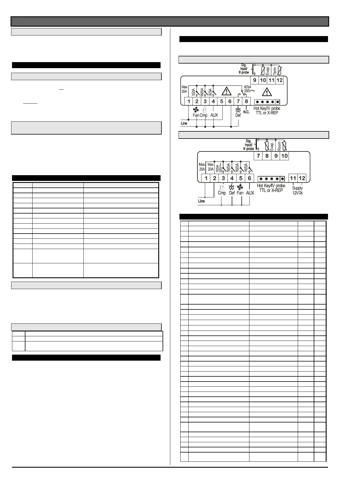
16. CONNECTIONS
The X-REP output excludes the TTL output.. It’s present in the following codes:
XR70CX- xx2xx, XR70CX –xx3xx;
16.1 XR70CX – 8A OR 16A COMP. RELAY - 12VAC/DV OR 24 VAC/DV
NOTE: The
compressor relay is
8(3)A or 16(6)A
according to the
model.
24Vac/dc supply:
connect to the
terminals 5 and 6.
16.2 XR70CX –4 X 16A - 12VAC/DC
17. DEFAULT SETTING VALUES
Lab
Name Range °C/°F Level
Set
Set point LS÷US -5.0 - - -
rtc
Real time clock menu - - Pr1
Hy
Differential
0,1÷25.5°C/ 1÷ 255°F
2.0 Pr1
LS
Minimum set point
-50°C÷SET/-58°F÷SET
-50.0 Pr2
US
Maximum set point
SET÷110°C/ SET ÷ 230°F
110 Pr2
Ot
Thermostat probe calibration
-12÷12°C /-120÷120°F
0.0 Pr1
P2P
Evaporator probe presence n=not present; Y=pres. Y Pr1
OE
Evaporator probe calibration
-12÷12°C /-120÷120°F
0.0 Pr2
P3P
Third probe presence n=not present; Y=pres. n Pr2
O3
Third probe calibration
-12÷12°C /-120÷120°F
0 Pr2
P4P
Fourth probe presence n=not present; Y=pres. n Pr2
O4
Fourth probe calibration
-12÷12°C /-120÷120°F
0 Pr2
OdS
Outputs delay at start up 0÷255 min 0 Pr2
AC
Anti-short cycle delay
0 ÷ 50 min
1 Pr1
rtr
P1-P2 percentage for regulation 0 ÷ 100 (100=P1 , 0=P2) 100 Pr2
CCt
Continuos cycle duration 0.0÷24.0h 0.0 Pr2
CCS
Set point for continuous cycle (-55.0÷150,0°C) (-67÷302°F) -5 Pr2
COn
Compressor ON time with faulty probe
0 ÷ 255 min
15 Pr2
COF
Compressor OFF time with faulty probe
0 ÷ 255 min
30 Pr2
CF
Temperature measurement unit
°C ÷ °F
°C Pr2
rES
Resolution
in=integer; dE= dec.point
dE Pr1
Lod
Probe displayed
P1;P2
P1 Pr2
rEd
2
X-REP display P1 - P2 - P3 - P4 - SEt - dtr P1 Pr2
dLy Display temperature delay 0 ÷ 20.0 min (10 sec.) 0 Pr2
dtr P1-P2 percentage for disply 1 ÷ 99 50 Pr2
tdF
Defrost type
EL=el. heater; in= hot gas
EL Pr1
dFP
Probe selection for defrost termination nP; P1; P2; P3; P4 P2 Pr2
dtE
Defrost termination temperature
-50 ÷ 50 °C
8 Pr1
IdF
Interval between defrost cycles
1 ÷ 120 ore
6 Pr1
MdF
(Maximum) length for defrost
0 ÷ 255 min
30 Pr1
dSd
Start defrost delay
0÷99min
0 Pr2
dFd
Displaying during defrost
rt, it, SEt, DEF
it Pr2
dAd
MAX display delay after defrost 0 ÷ 255 min 30 Pr2
Fdt
Draining time 0÷120 min 0 Pr2
dPo
First defrost after startup n=after IdF; y=immed. n Pr2
dAF
Defrost delay after fast freezing 0 ÷ 23h e 50’ 0.0 Pr2
Fnc
Fan operating mode C-n, o-n, C-y, o-Y o-n Pr1
Fnd
Fan delay after defrost 0÷255min 10 Pr1
Fct
Differential of temperature for forced
activation of fans
0÷50°C
10 Pr2
FSt
Fan stop temperature -50÷50°C/-58÷122°F 2 Pr1
Fon Fan on time with compressor off 0÷15 (min.) 0 Pr2
FoF Fan off time with compressor off 0÷15 (min.) 0 Pr2
FAP
Probe selection for fan management nP; P1; P2; P3; P4 P2 Pr2
ALc
Temperat. alarms configuration
rE= related to set;
Ab = absolute
Ab Pr2

 Loading...