6
EN
Introduction
The E-Port Development Kit includes an E-Port Adapter Board (incompatible with
SkyPort or X-Port), providing a ready-to-use platform for developers. The adapter
board can be used to develop payload devices for compatible DJI
TM
aircraft, or be
integrated into payload products.
Visit https://developer.dji.com/payload-sdk/ for more information on supported
DJI aircraft and product usage.
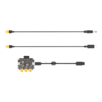
Port Description (Figure
Ⅰ
)
1. XT30 Power Output Port (12 V)
2. XT30 Power Output Port (5 V)
3. XT30 Power Output Port (VCC)
4. E-Port Switch
5. E-Port Connector
6. Power Indicator
7. Pin Header Power Output Port
8. UART/PPS Signal Port
9. USB 2.0 Port
10. USB ID Switch
Installation and Connection
1. As shown in Figure Ⅱ , remove the pin header protector. If only the UART/PPS
signal port is used, insert the pin header protector to the pin header power
output port to avoid short circuits.
2. As shown in Figure Ⅲ , connect the adapter board with the aircraft and the
payload device (M350 RTK is used as an example):
a. Select a XT30 power output port according to the actual payload rated
voltage.
b. Connect the XT30 power output port to the power port of the payload device
using the X
T30 po
wer cable.
c. Connect the E-Port Connector of the adapter board to the E-Port of the
aircraft using the E-Port Coaxial Cable. Note that the B side of the coaxial
cable and the aircraft heading should be as shown in the figure.
3. Toggle the E-Port switch to On to enable the E-Port connector. Toggle the